








 Contact Platform Support
 Help Center
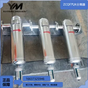
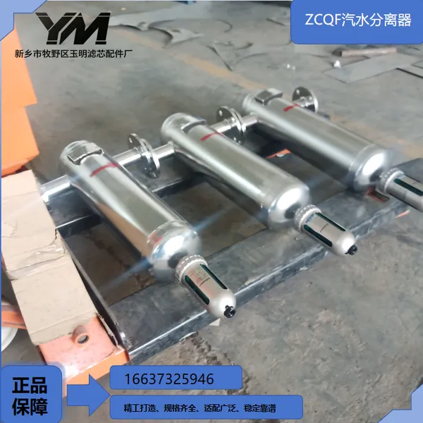
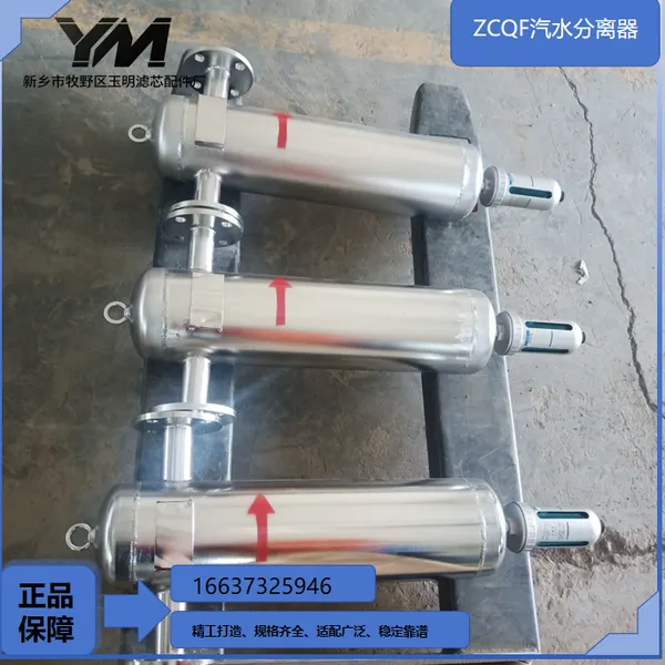
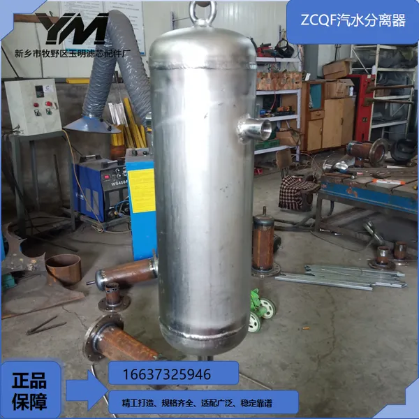
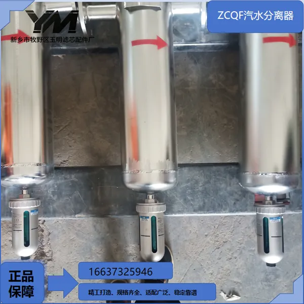
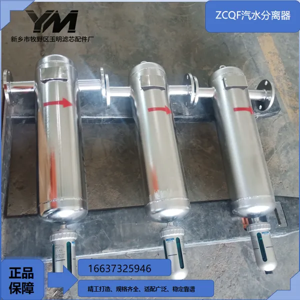
ZCQF Steam-Water Separator

Product Spotlights


Related Products
ZCQF Steam-Water Separator
1 Product Overview
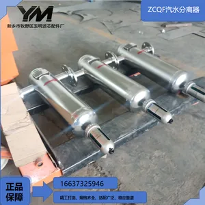
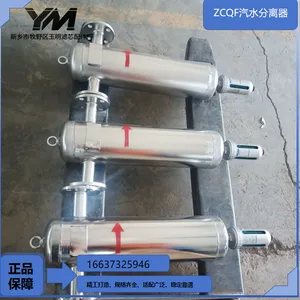
ZCQF Steam-Water Separator is a centrifugal swirling gas-liquid separation equipment, widely installed at boiler steam outlets, thermal pipe networks, post-compressor pipelines and process gas pipelines of vacuum systems. During transportation, wet steam and compressed air carry a large amount of condensed mist and liquid water. Liquid medium entering pipelines and heat exchange equipment easily causes water hammer impact, equipment erosion, reduced heat transfer efficiency and accelerated internal pipeline corrosion.Liquid-laden gas tangentially enters the separator cylinder. Built-in swirl guide structure forces medium to rotate at high speed. Droplets and solid particles with higher density are thrown to cylinder inner wall under centrifugal force, collide and coalesce into water flow, sink to the bottom liquid collection chamber along cylinder wall and are discharged continuously through drainage devices. Dry and clean gas flows upward through central channel to downstream processes.The equipment completes steam-water separation via pure physical centrifugal force without any filter consumables. It resists impact from solid impurities and is not easy to block for long-term stable continuous operation. Manufactured strictly in accordance with pressure vessel standards with multiple material and pressure grade options. As mainstream pre-dehydration protection equipment for steam and compressed air systems, it is widely used in thermoelectricity, food, pharmacy, chemical industry, printing and dyeing, papermaking and air compression supporting industries.
2 Main Structural Composition
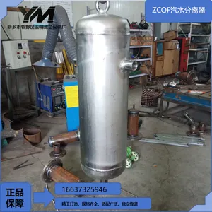
Pressure-bearing Cylinder HousingMain materials include Q235-B carbon steel with high-temperature anti-corrosion coating, 304 stainless steel and 316L stainless steel. The cylinder is integrally rolled and welded and subjected to hydraulic strength and tightness tests before delivery. Standard inlet and outlet flanges are arranged on both sides, supporting GB PN16, PN25 and ANSI standards. Liquid collection space is reserved at the bottom equipped with drain connections. Large-size models can be fitted with manholes for convenient inspection and maintenance of internal swirl components. Lifting lugs are reserved for vertical models for hoisting.
Built-in Swirl Guide AssemblyCore separation component. Spiral guide vanes are precisely arranged to guide gas flow to form stable high-speed swirling flow field and maximize centrifugal separation efficiency. The assembly is firmly welded with the cylinder with high temperature resistance and resistance to continuous airflow impact. Droplets continuously collide and converge on cylinder wall during gas rotation to avoid secondary entrainment of fine mist by airflow.
Bottom Liquid Collection & Flow Guide ChamberSedimentation liquid collection area is arranged at the lower part of housing. The inner wall diversion slope guides condensed water to converge to drain port and prevents local water retention. The gas phase buffer zone is reasonably arranged to reduce secondary atomization risk and ensure stable upward outflow of dry gas.
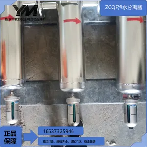
Matching Drain ConnectionStandard drain port at the bottom can be matched with manual blowdown ball valves, float steam traps and automatic drainers to continuously discharge accumulated condensate, maintain safe liquid level inside the chamber and prevent water vapor backflow caused by liquid level flooding.
Equipment Support Base / Lifting Lug (Optional)Standard vertical models are equipped with floor support bases; models for overhead pipe gallery installation are fitted with lifting lugs to support suspended pipeline installation, suitable for overhead pipeline layout.
3 Working Principle
Wet gas carrying water mist and liquid droplets enters the inner cavity of ZCQF separator tangentially from inlet. Medium forms high-speed swirling flow after passing through swirl guide vanes.Gas features low density and inertia and continuously flows upward along central channel of cylinder. Liquid mist and condensed droplets have higher density and are continuously thrown onto cylinder inner wall under centrifugal force. Numerous tiny droplets collide constantly and coalesce to form continuous water film, flow down along cylinder wall by gravity and finally converge into the bottom liquid collection chamber.Dry and clean steam or compressed air continuously flows toward outlet and is delivered to rear pipe network. Condensate inside liquid collection chamber is discharged continuously or regularly through bottom drainage devices. Within reasonable medium flow range, the equipment maintains efficient steam-water separation. The swirling structure still maintains stable droplet capture capacity under normal load fluctuation conditions.
4 Basic Technical Parameters
Applicable medium: saturated steam, superheated steam, compressed air, process gas without strong corrosionHousing material: anti-corrosion carbon steel / 304 stainless steel / 316L stainless steelDesign pressure: 1.0MPa, 1.6MPa, 2.5MPa; non-standard customization available for high-pressure conditionsDesign temperature: ≤300℃Separation efficiency: ≥98% (liquid mist droplets ≥5μm)Pressure loss: ≤2kPaConnection type: flange connection (GB & ANSI flange optional)Installation mode: vertical floor installation / pipeline suspended installationNominal diameter: full specifications DN25~DN1000
5 Core Product Advantages
Multi-stage swirling centrifugal separation principle without filter cartridges or screens, eliminating blockage caused by aging consumables and greatly cutting long-term maintenance costs.
Adaptable to gas flow fluctuation with stable dewatering performance under variable load. Separation effect is obviously improved compared with simple gravity separators.
Low operation pressure drop, avoiding insufficient system gas supply and guaranteeing stable pressure of the whole steam and compressed air pipe network.
Rich material solutions: carbon steel version for ordinary steam working conditions; stainless steel housing for humid and slightly corrosive working conditions.
Effectively eliminate water hammer in steam pipelines and protect turbines, valves, heat exchangers and drying equipment from droplet impact damage.
Improve steam dryness, raise thermal efficiency of heat exchange equipment and save system energy consumption.
Simple and robust structure without internal moving parts, long service life, suitable for uninterrupted all-year continuous production conditions.
Flexible installation modes including floor mounting and suspension layout, adapting to workshop pipe gallery and overhead pipeline arrangement.
Full specifications customized according to on-site pipeline parameters including diameter, pressure and cylinder size.
Complete unit delivered from factory. On-site construction only requires flange and drain pipeline connection with fast commissioning and short construction cycle.
6 Installation, Commissioning, Operation and Maintenance Specifications
Confirm flow direction marks before installation and connect pipelines strictly following inlet and outlet orientation. Shut-off valves are recommended before and after equipment for offline maintenance. Keep supports horizontal and stable for vertical floor installation; ensure uniform force on lifting lugs for suspended installation. Install sealing gaskets between flanges and fasten all bolts diagonally and evenly to prevent gas leakage.Open front-end valve slowly for initial startup to avoid instantaneous high-speed airflow impacting internal swirl components. Monitor drainage status of bottom drainage device during initial operation to confirm continuous normal discharge of condensate.Daily inspection focuses on air leakage at cylinder welding seams and flanges. Regularly overhaul steam traps and automatic drainers to prevent blockage and failure, avoiding secondary water vapor entrainment caused by excessive liquid level inside the chamber.During long-term shutdown maintenance, close front and rear shut-off valves, release pressure and cool down before opening manholes, clean sediment inside cylinder and inspect corrosion of swirl vanes. Carry out anti-corrosion repair when necessary. Long-term operation exceeding design pressure and temperature is prohibited.
7 Common Faults and Solutions
Poor separation performance with continuous massive water carryover in rear pipelinesCauses: gas flow velocity far exceeding rated operating condition; blocked drain device leading to high liquid level in collection chamber; deformed swirl components; wrong installation of inlet and outlet pipelines.Solutions: calculate gas flow and replace larger-size separator if necessary; clean and repair steam traps; open tank to inspect and restore swirl vanes; check medium flow direction and reconnect pipelines.
Obvious pressure rise of the system and large air supply resistanceCauses: excessive internal sediment blocking flow channels; front and rear valves not fully opened; undersized nominal diameter selected.Solutions: shut down and open tank to clean internal sediment of cylinder; fully open pipeline valves; recalculate working conditions and upgrade equipment diameter.
Abnormal drainage and continuous water accumulationCauses: stuck and blocked steam trap; foreign matter blocking drain pipeline; undersized drain diameter.Solutions: disassemble, clean or replace drainage device; dredge drain pipeline; optimize specification of drain pipeline.
Leakage at flanges and cylinder welding seamsCauses: aging and damaged sealing gaskets; loose bolts due to thermal expansion; corrosion thinning of welding areas.Solutions: install brand-new high-temperature resistant sealing gaskets; retighten bolts regularly under high temperature conditions; detect corroded areas, perform repair welding and reapply anti-corrosion treatment.
8 Standard Supply List and Optional Accessories
Standard Supply List
Pressure-bearing cylinder housing, built-in swirl guide assembly, inlet and outlet flanges, liquid diversion structure, equipment support base and connecting fasteners.
Optional Accessories
Steam trap, automatic drainer, inspection manhole, liquid level monitoring port, lifting lug assembly, ANSI flange, thermal insulation cladding and blowdown ball valve.


Send Inquiry to This Supplier


You May Also Like
-
T-type StrainerNegotiableMOQ: 1 Unit
-
OF7 Portable Filtration UnitNegotiableMOQ: 1 Unit
-
Cyclone Degassing Dirt SeparatorNegotiableMOQ: 1 Unit
-
Hand Brush Basket StrainerNegotiableMOQ: 1 Unit
-
Precision Security FilterNegotiableMOQ: 1 Unit
-
High Flow Security FilterNegotiableMOQ: 1 Unit
-
Cyclone DesanderNegotiableMOQ: 1 Unit
-
Horizontal Self-cleaning FilterNegotiableMOQ: 1 Unit
-
Multi-core Self-cleaning StrainerNegotiableMOQ: 1 Unit
-
Hand Brush Y-type StrainerNegotiableMOQ: 1 Unit


