

Hydraulic Motor Test Bench, Hydraulic Motor Test System, Beijing Haibohua
Related Products
-
 Hchl-202 Load Cell, Spoke Type Tension and Compression Sensor, CustomizableUS$ 69.23 - 107.69MOQ: 1 Piece
 -
Hcnj-101 Dynamic Torque Sensor for Torque and Rotational Speed Measurement, Non-contact Rotary Torque SensorUS$ 523.08 - 553.85MOQ: 1 Set
-
Torque Sensor Dedicated for Bottle Valve Loading and Unloading Machine and Gas Cylinder DetectionUS$ 569.23 - 584.62MOQ: 1 Piece
-
Factory Direct Sales of Wireless Pressure Transmitters and Wireless Temperature Transmitters, Capable of Transmitting up to 3000 MetersNegotiableMOQ: 0 Unit
-
3051 Capacitive Differential Pressure Transmitter, Pressure Transmitter With Capacitive Liquid Crystal Display and Hart ProtocolUS$ 215.38 - 230.77MOQ: 1 Piece
Overview
A hydraulic motor is an actuator in a hydraulic system. It converts the hydraulic pressure energy provided by the hydraulic pump into mechanical energy (torque and speed) of its output shaft. For motor manufacturers or users, hydraulic motor testing is necessary to determine the mechanical characteristics of the motors they produce or use.
The hydraulic motor test bench consists of a hydraulic station, a hydraulic motor, an HCNJ-101 torque sensor,eddy currentbrake, and a measurement and control system. It can test the torque, speed, and power of the hydraulic motor; the inlet pressure, outlet pressure, and pressure difference; the circulating flow, leakage flow, volumetric efficiency, and overall efficiency; the inlet and outlet temperatures, and the temperature difference.
Functions of the Hydraulic Motor Test Bench
Simulate loading with continuously adjustable loading torque;
Detect the input oil flow and pressure of the hydraulic motor;
Detect the output torque, speed, and power of the drilling tool;
The measuring instrument displays all measured parameters in real-time;
Communicate with the computer;
Manual loading or computer loading;
Automatically collect pressure, flow, torque, speed, and power parameters and calculate the efficiency;
Automatically generate parameter tables, correlation curves, and reports, which can be stored and printed.
Schematic Diagram of the Structure of the Hydraulic Motor Test Bench
Schematic Diagram of the Installation of the Flowmeter and Pressure Sensor
Main configurations and functions of the hydraulic motor test bench
1. Cast iron installation flat plate: Provides an installation reference for installing all mechanical devices to ensure installation accuracy; Ensures sufficient rigidity, guarantees no deformation under full load, and reduces vibration and noise; Equipped with a scraped plane for the sliding bracket to drive the tested oil pump to move axially along the test bench.
2. Movable sliding bracket screw propulsion mechanism: Allows the customer to fix the tested motor on the sliding bracket through a transition flange; Can drive the tested motor to move axially to connect or disconnect with the main shaft of the dynamometer.
3. Flow sensor: Measures the flow rate input to the drilling tool.
4. Pressure sensor: Measures the pressure input to the drilling tool.
5. Magnetic powder brake and matching high fixture: Simulate loading on the tested component; Adjust the center height to meet the coaxiality requirements of the sensor.
6.Coupling for the magnetic powder brake and torque speed sensor: Transmit torque; Buffer and absorb vibration; Protect the sensor.
7.Torque speed sensor: Measure the torque, speed, and power output by the motor;
8.Flow measuring instrument: Receive signals from the flow sensor, display the detected parameters, and send the parameters to the computer
9.Pressure measuring instrument: Receive signals from the pressure sensor, display the detected parameters, and send the parameters to the computer
10.Torque speed power measuring instrument: Receive signals from the torque speed sensor, display the detected parameters, and send the parameters to the computer
11.Loading controller: Receive computer control and send corresponding excitation current to control the magnetic powder brake to load as required
12.Industrial computer and data acquisition system: Run the software and collect detection parameters
13. Software: Manually load or load via computer; Automatically or manually collect parameters such as pressure, flow, torque, rotational speed, and power, and calculate efficiency; Automatically generate parameter tables, correlation curve graphs, and reports, which can be stored.
14. Vertical dedicated instrument cabinet: Install all measurement and control instruments.
Software interface of the hydraulic motor test system
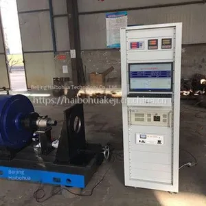
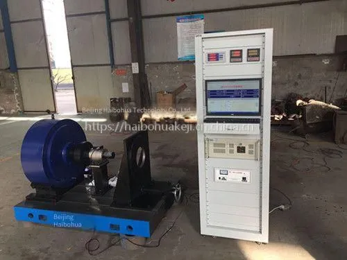
System photos

Send Inquiry to This Supplier


You May Also Like
-
3051 Differential Pressure Transmitter, Single Flange lt Type, With hc Diaphragm or Tantalum Diaphragm, Hart Protocol, Beijing Haibo HuaUS$ 261.54MOQ: 1 Piece
-
Actuator Torque Test Bench, Valve Torque Test Bench, Vertical InstallationUS$ 2769.23MOQ: 1 Set
-
Electric Motor Test Bench, Hydraulic Motor Test Bench, Haibo HuaUS$ 2769.23MOQ: 1 Set
-
Permanent Magnet Motor Test Bench and Motor Performance Testing System, Haibo HuaNegotiableMOQ: 0 Set
-
Motor Drag Test Bench Testing SystemUS$ 2769.23MOQ: 1 Set
-
Static Torque Sensor With Through Slot, Stationary Torsion Sensor, HaibohuaUS$ 69.23 - 73.85MOQ: 1 Piece
-
Clutch Performance Test Bench, Beijing Haibo HuaNegotiableMOQ: 0 Set
-
Hchz - 101 Column Type Tension and Compression Sensor With Large Range and External Thread, Beijing HaibohuaUS$ 123.08MOQ: 1 Piece
-
Disc Torque Sensor, Double Flange Dynamic Torque Sensor, Beijing HaibohuaUS$ 707.69MOQ: 1 Piece
-
Torque Test Bench for Electric Valve ActuatorsNegotiableMOQ: 0 Set


