

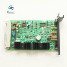
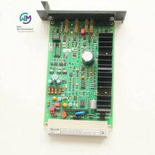
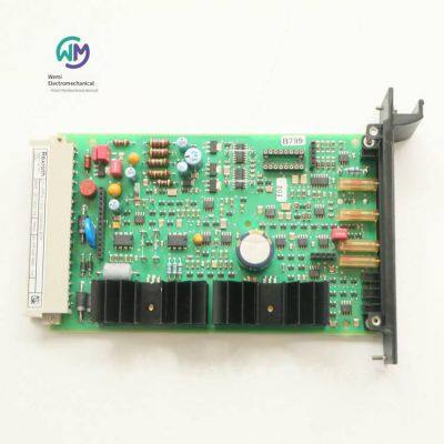
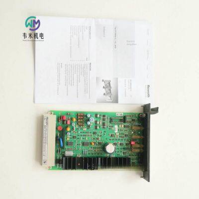
Rexroth Proportional Valve Amplifier Board 0811405104


Related Products
-
 Aventics Pull Rod Cylinder 0822343004US$ 187.69 - 190.77MOQ: 1 Piece
 -
Aventics Filter Pressure Regulator R412009210US$ 212.31 - 215.38MOQ: 1 Piece
-
German Aventics Valve Island R480034030US$ 938.46 - 953.85MOQ: 1 Piece
-
Rexroth Pressure Reducing Valve Zdr6dp2-4x/25ymUS$ 146.15 - 150.77MOQ: 1 Piece
-
Rexroth Stacked Pressure Reducing Valve Zdr6dp2-43/210ymUS$ 104.62 - 107.69MOQ: 1 Piece
Rexroth proportional valve amplifier board 0811405104, the main product of Shanghai Weimi Mechanical & Electrical Equipment Co., Ltd. Sales hotline: 13524123009; Contact person: Lei Qing; Product real-shot pictures, original genuine products, in-stock inventory, affordable prices; We sincerely welcome new and old customers to consult and purchase!
Rexroth REXROTH valve amplifiers for proportional pressure valves, proportional flow valves, and regulating valves
VT-VRPA1-537-1X/V0/...
0811405097 VT-VRPA1-537-10/V0/PV
0811405104 VT-VRPA1-537-10/V0/QV-RTP
Component series 1X
Analog, European board format
Suitable for the following types of valves: DBEB10Z, DREB10Z, DBETBX, 4WRP10EA
Final stage for closed-loop control
Closed-loop position control with PID characteristics
Fast excitation and fast power-off with short drive time
Gating input
Short-circuit protected output
Adjustable zero potential and sensitivity
Cable breakage recognition for the actual value cable
The amplifier board can only be plugged and unplugged after power-off.
The distance from antennas and radio systems must be at least 1 m.
Do not lay coils and signal lines near the power cable.
We recommend using shielded cables as signal lines and coil wires.
The cable shield must be centrally connected to the electrical cabinet, and the length should be as short as possible.
Do not connect the valve coil to self-oscillating diodes or other protection circuits.
The cable length and cross-section must comply with the specifications in the technical data.
Wiring information
The power supply zero b2 and the control zero b12 will be bridged.
If the power supply device is
If the distance is > 1 m, ground the control zero separately.
Rexroth REXROTH pilot-operated proportional pressure reducing valves
DRE(M) 10, DRE(M) 20
R901279577 DREM10-61/200YG24-8K4M
Size 10, 25
Component series 6X
Maximum working pressure 315 bar
Maximum flow rate 300 l/min
Installation position Any
Weight 4.7kg 6kg
Storage temperature range -20 … +80℃
Ambient temperature range -20 … +70℃
Pilot flow 0.8l/min
High flow 200l/min 300l/min
Hydraulic oil temperature range -20 … +80℃
Viscosity range 15 … 380mm²/s
Maximum allowable contamination level of hydraulic oil, cleanliness class according to ISO 4406 (c) Class 20/18/15 according to ISO 4406 (c)
Hysteresis ± 3.5%
Repeatability
Linearity ± 2%
Manufacturing tolerance of the pressure characteristic curve of the control value ± 3.5
Step response 10 ... 90% ≈ 130ms
Features
Valve for reducing system pressure
Operated by a proportional solenoid
Proportional solenoid with rotatable and detachable coil
For subplate mounting: Oil port mounting surface complies with ISO 5781
Third oil passage from A to Y (φ 7.5 mm)
Linearized pressure/given value characteristic curve
Good transient response
Optional check valve can be installed between A and B
Optional maximum pressure limit
Valves of type DRE(M) belong to pilot-operated pressure reducing valves. These valves can be used to reduce the working pressure.
The basic components of these valves are a pilot control valve with a proportional solenoid, a main valve with a main spool, and an optional check valve.
Model DRE...
The pressure in channel A can be set according to the control value by the proportional solenoid.
In the rest position – i.e., when there is no pressure in channel B – the spring holds the main spool in its initial position. The connection from channel B to channel A is closed. Thus, start-up jumps can be avoided.
The pressure applied in channel A acts on the face of the main spool through the orifice. The pilot oil flows from channel B through the orifice to the constant current control, which keeps the pilot flow constant, regardless of the pressure drop between channels A and B. The pilot flow flows from the constant current control into the spring chamber, passes through the orifice and, flows through the valve seat into channel Y and returns from there. The required pressure in channel A is preset by the relevant amplifier. The proportional solenoid moves the valve frame towards the valve seat and limits the pressure in the spring chamber to the set value. If the pressure at channel A is lower than the preset control value, the higher pressure in the spring chamber will move the main spool to the right. The connection from B to A is opened. If the set pressure at A has been reached, the forces at the main spool are in balance - the main spool is in the control position.
Pressure at the valve core end face of Channel A = Pressure at the valve core end face of the spring chamber – Spring force
If in a vertical hydraulic oil column (e.g., the hydraulic cylinder piston in the cut-off position), to reduce the pressure at A (for example), a lower control value can be preset through the control electronics. In this way, a lower pressure value can be pre - selected, and this pressure value will immediately appear in the spring chamber. The higher pressure value at A acting on the surface of the main valve core will push the main valve core in the direction of the protective plug to the cut-off position. The connection from A to B is blocked, and the connection from A to Y is opened. The force at the spring currently acts in the opposite direction to the hydraulic force on the surface of the main valve core. At this position of the main valve core, the hydraulic oil can flow from Channel A to Y through the control edge and enter the return flow.
When the pressure at A drops to the sum of the pressure in the spring chamber and the ∆p of the spring, the main valve core will close the large control hole in the socket at the control edge from A to Y.
The remaining pressure difference relative to the new control value at A is about 10 bar. The current pressure can only be unloaded through the control hole. In this way, a good transient response can be achieved without pressure overshoot. To achieve free return flow from Channel A to Channel B, a check valve can be optionally installed. Part of the filling flow at Channel A can also flow into the return flow through the control edge from the opened main valve core A to Y.
Model DREM...
In order to provide hydraulic protection and prevent an unallowable high electrical control current from appearing on the proportional electromagnet, which causes excessive pressure at port A, a spring - loaded relief valve can be optionally installed to limit the maximum pressure. This maximum pressure limit is a preset value based on the relevant pressure level.
Rexroth REXROTH Pilot - operated Proportional Relief Valve
(Z)DBE 6, (Z)DBEE 6
R901335463 ZDBEE6VP2 - 21/315G24K31A1M
Specification 6
Component series 2X
Maximum working pressure 350 bar
Maximum flow rate 30 l/min
Installation position Any
Weight 2.5kg
Storage temperature range -20 … +80℃
Ambient temperature range -20 … +70℃
Return pressure Return pressure at port A, external pilot oil
Maximum flow rate 30l/min
Hydraulic oil temperature range -20 … +80℃
Viscosity range 15 … 380mm²/s
Maximum allowable contamination degree of hydraulic oil, cleanliness class according to ISO 4406 (c) Class 20/18/15 according to ISO 4406 (c)
Hysteresis ± 3%
Repeatability
Linearity ± 3.5%
Manufacturing tolerance of the control value pressure characteristic curve, related to the hysteresis characteristic curve and pressure increase
Hydraulic oil: HL, HLP
Suitable sealing materials: NBR/FKM
Maximum coil current: 1760mA
Electromagnetic coil resistance
Low temperature value at 20 °C: 5.5Ω
Maximum high temperature value: 8.05Ω
Duty cycle: 100%
Power supply: 24VDC
Features
Pilot-operated proportional valve for limiting system pressure, separating and relieving pressure back to the oil tank
Operated by a proportional electromagnet
Proportional electromagnet with rotatable and detachable coil
For subplate mounting or stacked valve plate design: Oil port mounting surface complies with ISO 4401-03-02-05 and DIN24340
Both the valve and control electronics are from the same source
External control electronics for models DBE and ZDBE
Linearized pressure/given value characteristic curve
Models DBEE and ZDBEE with integrated electronics (OBE)
Small manufacturing tolerance of the set value pressure characteristic curve
The pilot-operated proportional relief valves of type (Z)DBE are activated by a proportional electromagnet. These valves can be used to limit the system pressure. Depending on the electrical control value, these valves can be used to steplessly set the system pressure to be limited. The basic structure of these valves consists of a pilot control stage and a main stage. The pilot control assembly consists of a proportional electromagnet, a valve frame, and a valve seat. The main stage consists of a housing and a main spool assembly. The proportional electromagnet converts the current proportionally into mechanical force. An increase in current will result in a corresponding increase in the magnetic force of the coil. The system pressure can be set according to the control value through the proportional electromagnet. The pressure applied by the system at channel P acts on the right side of the main spool assembly. At the same time, the system pressure will act on the spring-loaded side of the spool through the control oil circuit equipped with a nozzle. Through the valve seat of the pilot pipeline, the pressure at the valve frame of the spring chamber can overcome the force of the proportional electromagnet. When the pressure reaches the preset value, the valve frame will be lifted from the valve seat. At this time, the pilot oil (depending on the model) can drain oil out through port A (Y) or drain oil to the internal oil tank, which will also limit the pressure on the spring-loaded side of the main spool. If the system pressure continues to rise slowly, the high pressure on the right side of the spool will push the spool to the left to the control position from P to T. At the minimum control current (corresponding to the zero control value), the minimum set pressure will be set.
Attention!
Prevent the fuel tank pipeline from running under no-load conditions. Under the corresponding installation conditions, a preload valve (with a preload pressure of approximately 1 bar) must be installed.
The (Z)DBEE type pilot-operated proportional relief valve is activated by a proportional electromagnet. This valve can be used to limit the system pressure. Depending on the electrical control value, these valves can be used to steplessly set the system pressure to be limited. The basic structure of these valves consists of a pilot control stage and a main stage. The pilot control assembly is composed of a proportional electromagnet, a valve frame, and a valve seat. The proportional electromagnet is also equipped with a housing with control electronics. The power supply voltage and the control value voltage are applied to the connector. The control value-pressure characteristic curve has been adjusted according to very low manufacturing tolerances at the factory. The main stage consists of a housing and a main spool assembly. The proportional electromagnet converts the current into mechanical force proportionally. An increase in current will lead to a corresponding increase in the magnetic force of the coil. The system pressure can be set according to the control value through the proportional electromagnet. The pressure applied by the system at channel P acts on the right side of the main spool assembly. At the same time, the system pressure will act on the spring-loaded side of the spool through the control oil circuit equipped with a nozzle. Through the valve seat of the pilot pipeline, the pressure at the valve frame of the spring chamber can overcome the force of the proportional electromagnet. When the pressure reaches the preset value, the valve frame will be lifted from the valve seat. At this time, the pilot oil (depending on the model) can drain oil outward through the oil port A (Y) or drain oil to the internal fuel tank, which will also limit the pressure on the spring-loaded side of the main spool. If the system pressure continues to rise slowly, the high pressure on the right side of the spool will push the spool to the left to the control position from P to T. When the control current is small (corresponding to a zero control value), a small set pressure will be set.
Attention!
Prevent the fuel tank pipeline from running under no-load conditions. Under the corresponding installation conditions, a preload valve (with a preload pressure of approximately 1 bar) must be installed.
R901304331 DBE6-21/100G24K4M
Rexroth direct-acting directional spool valve with electromagnetic activation
WE 6...E
Size 6
Component series 6X
Maximum working pressure 350 bar
Maximum flow rate (DC) 80 l/min
Maximum flow rate (AC) 60 l/min
Three-position four-way, two-position four-way, or two-position three-way models
Oil port mounting surface, compliant with ISO 4401-03-02-0-05 (with or without holes)
High-power coil, optionally rotatable by 90°
Electrical connection as a single or centered connection
Optional auxiliary operating device
Optional spool position monitoring
When the voltage is > 50 VAC or > 75 VDC, CE compliance meets the Low Voltage Directive 2014/35/EU
The electromagnetic coil is an approved component with a UR mark, conforming to UL 906, version 1982, optional
Certified by CSA, optional
The directional valves of the WE model are solenoid-operated directional spool valves, and this valve can be used as an electromagnetic assembly. They are used to control the start, stop, and direction of the flow.
The basic composition of this directional valve is a housing, one or two electromagnets, a control spool, and a return spring.
In the de-energized state, the control spool is held in the middle position or the initial position by the return spring (except for version "O").
When the electromagnet in the hydraulic oil is energized, the control spool moves from its rest position to the desired terminal position. This can emit the desired fluid direction according to the selected symbol.
After the electromagnet is turned off, the control spool will be pushed back to the middle position or the initial position (except for valves with an "OF" device and valves without spring type "O").
For auxiliary operation, the valve can be manually switched without energizing the magnet.
The hydraulic system must be properly vented to ensure normal operation.
Without spring return "O" (only applicable to symbols A, C, and D)
This type is a directional valve with two switching positions and two electromagnets without a device. Valves without spring return at the control spool have no definite initial position in the de-energized state.
Without spring return, with device "OF" (only applicable to symbols A, C, and D)
This type is a directional valve with two switching positions and two electromagnets with a device. The control spool is fixed in the corresponding switching position by the device. Therefore, during operation, there is no need to apply current to the electromagnet, which helps with energy-saving operation.
Model "73...A12" (soft switching behavior)
The combination of the control spool and the electromagnetic coil reduces the number of commutation strokes that occur when the valve opens or closes. Compared with the standard valve, the commutation stroke (measured as the acceleration value a) can be reduced by about 85%, depending on the model of the control spool (see "Acceleration value").
Note:
Pressure peaks in the drain lines connecting two or more valves may cause unexpected movement of the control spool in models with a device. It is recommended to lay a separate return line or install a check valve in the drain line.
Due to the design principle, internal leakage will occur in the valve, and the leakage amount will increase during the service life.
Throttle plug-in
According to the main working conditions, if the flow rate may exceed the performance limit of the valve during the switching process, a throttle plug-in will be required.
Order numbers and models of German Rexroth solenoid valves:
R900561180 3WE6A62/EG24N9K4
R900915873 3WE6A62/EG24N9K4/V
R900935575 3WE6A62/EG220N9K4/V
R900915672 3WE6A62/EW230N9K4
R978017740 3WE6A6X/EG24N9K4/62
R900948958 3WE6B62/EG24N9K4/V
R900907814 3WE6B9-62/EG24N9K4
R900561272 4WE6C62/EG24N9K4
R900901748 4WE6C62/EW110N9K4
R900908879 4WE6D62/EG110N9K4
R900944594 4WE6D62/EG110N9K4/V
R900561274 4WE6D62/EG24N9K4
R900564105 4WE6D62/EG24N9K4/V
R900908590 4WE6D62/EG24N9K4/B12
R900903081 4WE6D62/EG205N9K4
R900916984 4WE6D62/EG220N9K4
R901008688 4WE6D62/EG220N9K4/V
R900551704 4WE6D62/EW110N9K4
R900909559 4WE6D62/EW230N9K4
R901483086 4WE6D62/OFEG110N9K4/B12
R900567512 4WE6D62/OFEG24N9K4
R900903465 4WE6D62/OFEG24N9K4/V
R900920691 4WE6D62/OFEG220N9K4
R900922533 4WE6FB62/EG24N9K4
R900567997 4WE6J73-62/EG24N9K4/A12
R900931967 4WE6JA62/EG24N9K4/B08
R900903463 4WE6L62/EG24N9K4/V
R900577475 4WE6M62/EG24N9K4
R900571012 4WE6R62/EG24N9K4
R900905896 4WE6Y62/EW110N9K4
R900556472 4WE6Y62/EG24K4QMAG24
R900561276 4WE6Y62/EG24N9K4
R900909178 4WE6Y62/EG24N9K4/B08
R900917497 4WE6Y62/EG24N9K4/B10
R900922335 4WE6Y62/EG220N9K4
R900765505 4WE6Y62/EG26N2K4K
R901073870 3WE6A62/OFEG220N9K4
R901235381 4WE6D46-62/OFEG24N9K72LSO407
R900561274 4WE6D6X/EG24N9K4
R900574632 4WE6D62/EG24K4QMBG24
R900909559 4WE6D6X/EW230N9K4
R900546257 4WE6D73-62/EG24N9K4/A12
R901235374 4WE6D73-6X/EG24N9K72L/A12
R900927437 4WE6D73-62/EG24N9K4/A12B10
R900561278 4WE6E62/EG24N9K4
R900903464 4WE6E62/EG24N9K4/V
R900921477 4WE6E62/EG24N9K4/B10
R900558641 4WE6E62/EW110N9K4
R900912492 4WE6E62/EW230N9K4
R901259406 4WE6E73-62/EG24N9K72L/A12=AN
R900561280 4WE6EA62/EG24N9K4
R901162080 4WE6EB62/EG220N9K4
R901034409 4WE6E6X/BG24NXDZ2/V
R900551703 4WE6J62/EW110N9K4
R900908878 4WE6J62/EG110N9K4
R900561288 4WE6J62/EG24N9K4
R900901045 4WE6J62/EG24N9K4/B08
R900548271 4WE6J62/EG24N9K4/B10
R900922535 4WE6J62/EG24N9K4/B20
R900911762 4WE6J62/EW230N9K4
R900912079 4WE6J62/EW230N9K4/B10
R900548772 4WE6J62/EG24N9K4/V
R900922207 4WE6J62/EG220N9K4
R901235012 4WE6J62/EG24N9K72L
R900548271 4WE6J6X/EG24N9K4/B10
R900765511 4WE6J62/EG26N2K4K
R900561291 4WE6JB62/EG24N9K4
R900932917 4WE6JB62/EG24N9K4/V
R900561292 4WE6Q6X/EG24N9K4
R901235370 4WE6Q62/EG24N9K72L
R900940418 4WE6Y11-62/EG24N9K4
R900561286 4WE6H62/EG24N9K4
R900549534 4WE6HA62/EG24N9K4
R900561282 4WE6G62/EG24N9K4
R900912493 4WE6G62/EW230N9K4
R900561284 4WE6GA62/EG24N9K4
R900549534 4WE6HA62/EG24N9K4
R900578186 4WE6UA62/EG24N9K4
R901396248 4WE6U62/EG220N9K4/V
R901509281 4SEC6E2X/G24N9K4
Rexroth Insertion Joint 3P Z5L M 12-240V SPEZ
R901017022
Matching connector, 3 pins (2 + PE) EN 175301-803, with LED, black
For valves with plug K4. OEM accessory. For industrial use.
Supply voltage 12 … 240 V AC/DC
Electrical plug 3-pin device plug (2 + PE)
Electrical connection description 3-pin device connector (2 + PE), compliant with EN 175301-803
Weight [kg] 0.038
REXROTH Direct-acting directional spool valve with electromagnetic actuation
WE 6...H
Size 6
Component series 7X
Maximum working pressure 315 bar
Maximum flow rate 60 l/min
3-position 4-way, 2-position 4-way or 2-position 3-way models
Standard models
Port mounting surface compliant with DIN 24340, form A
DC coil with wet pins
Electromagnetic coil can be rotated
There is no need to open the pressure-tight sealed chamber when replacing the coil.
Electrical connection as a single connection
Implicit manual emergency operation
The directional valves of the WE model are directional spool valves operated by electromagnetic coils. These valves control the start, stop and direction of the fluid.
These directional valves are mainly composed of a housing, one or two coils, a control spool and one or two return springs. In the case of power failure, the control spool is fixed in the center position or the initial position by the return spring. The control spool is actuated by a coil with wet pins.
To ensure normal operation, please make sure to fill the pressure chamber of the coil with hydraulic oil!
The force of the coil acts on the control spool through the push rod and pushes the latter from its rest position to the desired terminal position. In this way, the desired flow direction can be released according to the symbol. After the coil is demagnetized, the return spring pushes the control spool back to its rest position.
Manual emergency operation can control the spool when the coil is not energized.
Order numbers and models of REXROTH solenoid valves from Germany:
R901089245 4WE6C70/HG24N9K4
R901087088 4WE6D70/HG24N9K4
R901087087 4WE6E70/HG24N9K4
R901108990 4WE6J70/HG24N9K4/B10
R901133322 4WE6HA70/HG24N9K4
R901089241 4WE6J70/HG24N9K4
R901108990 4WE6J70/HG24N9K4/B10
R901108705 4WE6JB70/HG24N9K4
Rexroth REXROTH Direct-acting directional spool valve with electromagnetic actuation
WE 10...E
Size 10
Component series 5X
Maximum working pressure 350 bar
Maximum flow rate 160 l/min
Three-position four-way, two-position four-way or two-position three-way models
Port mounting surface complies with ISO 4401-05-04-0-05
High-power coil, optional 90° rotation
Electrical connection as single or centering connection
Optional to be used with PWM connector (fast switching amplifier, energy-saving)
Optional auxiliary operating device
When the voltage is > 50 VAC or > 75 VDC, CE compliance meets the Low Voltage Directive 2014/35/EU
The electromagnetic coil is an approved component with UR mark, optional
Optional certification through CSA C22.2 139-13
The directional valve of the WE model is an electromagnetic coil-operated directional spool valve, which can be used as an electromagnetic component. This valve controls the start, stop and direction of the fluid.
The basic structure of this directional valve consists of a housing, one or two electromagnets, a control spool and a return spring. In the de-energized state, the control spool is held in the middle position or the initial position by the return spring (except for version "O"). When the electromagnet in the hydraulic oil is energized, the control spool moves from its rest position to the required end position. In this way, the required fluid direction can be issued according to the selected symbol.
After the electromagnet is turned off, the control spool will be pushed back to the middle position or the initial position (except for valves with "OF" device and valves without spring type "O").
Auxiliary operation can manually switch the valve when the magnet is not energized.
The hydraulic system must be properly ventilated to ensure normal function.
Without spring return "O" (only applicable to symbols A, C and D)
This model is a directional valve with two switching positions and two electromagnets without a device. The valve without spring return at the control spool has no definite initial position in the de-energized state.
Without spring return, with device "OF" (only applicable to symbols A, C and D)
This model is a directional valve with two switching positions and two electromagnets with a device. The control spool is fixed in the corresponding switching position by the device. Therefore, during operation, there is no need to apply current to the electromagnet, which helps in energy-saving operation.
Model "73...A12" (soft switching behavior)
The combination of the control spool and the electromagnetic coil reduces the number of commutation strokes that occur when the valve opens or closes.
Compared with standard valves, the commutation stroke (measured as the acceleration value a) can be reduced by approximately 85%, depending on the model of the control spool (see "Acceleration value").
Note:
Pressure peaks in the drain lines connecting two or more valves may cause unexpected movement of the control spool in models with actuators. It is recommended to lay separate return lines or install check valves in the drain lines.
Due to the design principle, internal leakage occurs in the valve, and the leakage amount will increase during the service life.
Throttle plug-in
Depending on the main working conditions, if the flow rate may exceed the performance limit of the valve during the switching process, a throttle plug-in will be required.
Order numbers and models of German Rexroth electromagnetic directional valves:
R900944371 4WE10D33/CG220N9K4/V
R901487117 4WE10C50/EW230N9K4/M
R900598925 4WE10D33/CW110N9K4
R900912496 4WE10D33/CW230N9K4
R900923393 4WE10D33/CW230N9K4/V
R901336181 4WE10D50/EG205N9K4/M
R901344560 4WE10D50/EG220N9K4/V
R901339383 4WE10D50/EG220N9K4/M
R901278760 4WE10D50/EG24N9K4/M
R901483529 4WE10D50/EW230N9K4/M
R901391200 4WE10D50/HG24N9K4/M
R901344562 4WE10D50/OFEG220N9K4/M
R901278763 4WE10D50/OFEG24N9K4/M
R901278761 4WE10E50/EG24N9K4/M
R901390857 4WE10E50/HG24N9K4/M
R900595532 4WE10EA33/CG24N9K4
R901278780 4WE10EB50/EG24N9K4/M
R901278768 4WE10G50/EG24N9K4/M
R901427832 4WE10G50/HG24N9K4/M
R900597986 4WE10H33/CG24N9K4
R901349517 4WE10HB50/EG24N9K4/M
R900593805 4WE10J33/CW230N9K4
R901278744 4WE10J50/EG24N9K4/M
R901401552 4WE10J50/HG24N9K4/M
R901327207 4WE10J50/EG205N9K4/M
R901278782 4WE10JA50/EG24N9K4/M
R901278784 4WE10R50/EG24N9K4/M
R901349519 4WE10RB50/EG24N9K4/M
R901333735 4WE10T50/EG24N9K4/M
R901391202 4WE10Y50/HG24N9K4/M
R900591664 4WE10D3X/OFCG24N9K4
R901391203 4WE10C51/HG24N9K4/M
R901391200 4WE10D51/HG24N9K4/M
R901390857 4WE10E51/HG24N9K4/M
R901427832 4WE10G51/HG24N9K4/M
R901427828 4WE10H51/HG24N9K4/M
R901427828 4WE10H52/HG24N9K4/M
R901401552 4WE10J51/HG24N9K4/M
R901391161 4WE10L50/HG24N9K4/M
R901278778 4WE10U50/EG24N9K4/M
Rexroth Direct-acting Directional Slide Valve with Electromagnetic Actuation
Z4WE 6
Specification 6
Component Series 3X
Maximum Working Pressure 315 bar
Maximum Flow Rate 50 l/min
Weight
Single Coil 1.2kg
Dual Coils 1.6kg
Temperature Range -20 … +50℃
Features
2/4-way and 3/4-way directional shut-off valves
Stack valves
Used as straight-through valves or short-circuit valves
Port mounting surface conforms to ISO 4401-03-02-0-05 (with or without holes)
AC or DC solenoids that switch in oil
Optional to be used with PWM connectors (fast-switching amplifiers, energy-saving)
Optional auxiliary operating device
Optional spool position monitoring
When the voltage is > 50 VAC or > 75 VDC, CE compliance meets the Low Voltage Directive 2014/35/EU
The Z4WE type directional valve is an electromagnetic coil-operated directional spool valve. This valve controls the start, stop and direction of the fluid.
The basic structure of this directional valve consists of a housing, one or two coils, a control spool and two return springs.
In the non-operating state, the control spool is held in the center position or the initial position by the return springs. The control spool is operated by the wet-pin coils.
The hydraulic system must be properly ventilated to ensure normal function.
The force of the coil acts on the control spool through the push rod and pushes it from the rest position to the required final position. In this way, the required flow directions from A② to A① and B② to B① are released.
After the coil is de-energized, the control spool is pushed back to the rest position by the return spring.
Optional manual emergency operation can move the control spool when the coil is not energized.
Note:
Due to design principles, internal leakage of the valve is inevitable, and the leakage amount will increase with the increase of service time.
Refer to Parameter Sheet 08012 for the allowable shock and vibration loads.
Precautions:
The solenoid valve will generate voltage peaks during closing. In order to prevent electromagnetic interference in the system and damage to the valve control, an interference protection circuit must be provided on the system side. Alternatively, a connector with an integrated interference protection circuit can be selected.
Precautions:
When establishing an electrical connection, the protective grounding wire (PE) must be correctly connected.
The wiring must be done in a way to relieve the tension!
The cable bundle coil is only suitable for the installed cable.
During operation, the connector should be locked. It must not be inserted or disconnected during normal operation with a load.
The cross-section of the protective grounding wire is equal to or larger than that of the power supply line.
The valve mounting surface must be connected to the protective grounding wire system.
Order numbers and models of German Rexroth solenoid valves:
R901087024 Z4WE6X252-31/EG24N9K4/V/60
R900936096 Z4WE6E68-3X/EG24N9K4/V
R900941535 Z4WE6E68-3X/EG24K4/V
Direct-acting directional spool valve with electromagnetic actuation
5-.WE
5-cavity model
Size 10
Component series 5X
Maximum working pressure 420 bar
Maximum flow rate 150 l/min
Three-position four-way, two-position four-way or two-position three-way models
Port mounting surface complies with ISO 4401-05-04-0-05
High-power coil, optional 90° rotation
Electrical connection as a single connection
Optional to be used with PWM connector (fast switching amplifier, energy-saving)
Optional auxiliary operating device
Optional spool position monitoring
When the voltage > 50 VAC or > 75VDC, CE compliance meets the Low Voltage Directive 2006/95/EC
Electromagnetic coil certified by UR to UL 429
Optional certification according to CSA C22.2 139-10
The 5-.WE type 5-cavity directional valve is an electromagnetic coil-operated directional spool valve with increased switching time. This valve controls the start, stop and direction of the fluid. The basic structure of these directional valves consists of a housing, one or two electronic coils, a control spool and a return spring.
In the case of power failure, the control spool is fixed in the center position or the initial position by the return spring (except for valves without spring "O").
When the wet-pin electronic coil is energized, the control spool moves from the rest position to the desired end position. In this way, the desired flow direction can be released according to the selected symbol.
After the electronic coil is turned off, the control spool will be pushed back to the center position or the initial position (except for valves with "OF" device and valves of type "O" without spring).
Manual emergency operation allows the valve to be manually switched without energizing the coil.
To ensure normal operation, make sure to fill the pressure chamber of the coil with hydraulic oil.
Throttle plug-in
When using a throttle plug-in in the channels P, A, B or T, the flow resistance at the valve will increase. According to the main working conditions, if the flow rate may exceed the performance limit of the valve during the switching process, a throttle plug-in will be required.
Without spring return "O" (only symbols A, C and D can be used)
This model is a directional valve with 2 spool positions and 2 electronic coils and without a device. Valves without spring return at the control spool have no definite initial position in the power-off state.
Without spring return, with device "OF" (only symbols A, C and D can be used)
This type of directional valve comes with 2 spool positions, 2 electronic coils, and a [device]. The [device] is used to lock the control spool in the relevant spool position. Therefore, during operation, there is no need to continuously apply current to the electronic coils, which helps with energy-saving operation.
Note:
If the valve is equipped with a [device], pressure peaks of two or more valves in the tank line may cause unexpected movement of the control spool! Therefore, we recommend providing a separate return line or installing a check valve in the tank line.
Impact on switching time
For the 5-cavity directional valve of type 5-.WE, the switching time can be delayed to 100 ms or even longer through the throttle screw "C" or the selected "A0." orifice. In this connection, the switching time is related to pressure, flow rate, and viscosity, depending on the installation situation. By restricting (throttling or using an orifice) in the connection channel between the two spring chambers, the switching time will be affected. During the switching process, the liquid volume in the connection channel will be discharged from one spring chamber to the other.
The T-channel is separated from the spring chamber to achieve soft switching.
Attention!
Only unscrew the adjustment spindle when it needs to be 3 mm higher than the nut.
Rexroth Direct-acting Directional Spool Valve with Electromagnetic Actuation
WE 6…B..XD
Size 6
Component series 6X
Maximum working pressure 315 bar
Maximum flow rate 60 l/min
Application areas comply with the explosion-proof directive 2014/34/EU: I M2; II 2G
Application areas comply with the technical regulation EAC TR CU 012/2011: I M2; II 2G
Valve explosion-proof protection type:
– Ex h I Mb X in accordance with EN 80079-38
– Ex h IIC T4 Gb X in accordance with EN 80079-36
Valve coil explosion-proof protection type:
– Ex db I Mb in accordance with EN 60079-1
– Ex db IIC T4 Gb in accordance with EN 60079-1
The electromagnetic coil is certified by IECEx
Three-position four-way, two-position four-way, or two-position three-way models
Intended for use in potentially explosive environments,
The oil port mounting surface complies with ISO 4401-03-02-0-05
DC coil with wet pins
Electrical connection with single connection and cable bundle coil
With manual emergency operation
The WE type directional valve is an electromagnetic coil-operated directional slide valve. This valve controls the start, stop, and direction of the fluid.
The basic components of this directional valve are the housing, one or two coils, the control spool, and one or two return springs.
In the non-operating state, the control spool is held in the center position or the initial position (except for the pulse spool) by the return spring. The control spool is operated by the wet pin coil.
The hydraulic system must be properly ventilated to ensure normal functioning.
The force of the coil acts on the control spool through the plunger and pushes it from the rest position to the desired end position. This releases the required flow directions P → A and B → T or P → B and A → T.
After the coil is de-energized, the control spool is pushed back to the rest position by the return spring.
Manual emergency operation can move the control spool when the coil is not energized.
Without spring return "O" (only applicable to symbols A, C, and D)
This model is a directional valve with two switching positions and two magnets without a lock. There is no defined switching position in the de-energized state.
Without spring return, with lock "OF" (pulse spool, only applicable to symbols A, C, and D)
This model is a directional valve with two switching positions, two magnets, and a lock. In this way, the two switching positions are alternately fixed, and the excitation of the magnets can be eliminated.
Note:
Due to design reasons, internal leakage of the valve is inevitable, and the leakage amount will increase with the increase of service time.
Rexroth electromagnetic-operated 2/2-way, 2/3-way, and 2/4-way directional seat valves
M-.SED6
Size 6
Component series 1X
Maximum working pressure 350 bar
Maximum flow rate 25 l/min
Features
Electromagnetic-operated direct-acting directional seat valve
Port mounting surface conforms to DIN 24340 form A (without holes)
Port mounting surface conforms to ISO 4401-03-02-0-05 (with holes)
Safe switching, also able to withstand long downtime under pressure
Wet pin DC coil with removable coil (a rectifier must be installed if it is an AC power supply)
The electromagnetic coil can be rotated 90°
When replacing the coil, there is no need to open the pressure-tight sealed cavity
Electrical connection as a single connection
With hidden manual emergency control, optional
Position sensing switch (contactless)
Product description
Two-position four-way directional seat valve
Two-position two-way and two-position three-way directional seat valves
The directional valve of model M-.SED is a direct-acting directional seat valve operated electromagnetically. This valve controls the start, stop and direction of the fluid, and is mainly composed of a housing, a coil, a valve seat and a closing element.
Manual emergency operation allows the valve to be switched without energizing the coil.
Basic principle (Two-position three-way directional seat valve)
The initial position of the valve (normally open "UK" or normally closed "CK") is determined by the arrangement of the spring. The cavity behind the closing element is connected to port P and is sealed off from port T. Therefore, the valve is pressure-compensated according to the actuating force (coil and spring).
With a special closing element, ports P, A and T can be loaded with a large working pressure (350 bar), and the fluid can flow in both directions (see the symbol)!
In the initial position, the closing element is pressed into the valve seat by the spring, and in the spool position, it is pressed into the valve seat by the coil. Therefore, the fluid is blocked.
With the two-position two-way directional seat valve, the return port is closed internally.
Two-position four-way directional seat valve
Two-position two-way and two-position three-way directional seat valves
The function of the two-position four-way directional seat valve can be achieved through a stacking valve plate called the Plus-1 plate below the two-position three-way directional seat valve.
Function of the Plus-1 plate
Initial position:
The main valve is not operated. The spring holds the closing element on the valve seat. Port P is blocked, and port A is connected to port T. The control oil circuit connects A and the larger area of the control spool, so it can be unloaded to the tank. The pressure applied through P will push the ball onto the valve seat. Therefore, P is connected to B, and A is connected to T.
Transition position:
After the main valve is activated, the closing element moves against the spring and is pressed into the valve seat. During this period, port T is blocked, and P, A and B are briefly connected together.
Switching position:
P is connected to A. Since the pump pressure acts on the larger area of the control spool via A, the ball is pressed into the valve seat. Therefore, B is connected to T, and P is connected to A. The ball in the Plus-1 plate has "positive spool overlap".
Attention!
When using a differential hydraulic cylinder, to avoid overpressure, the annular area of the hydraulic cylinder must be connected at A.
Throttle insert
According to the main working conditions, if the flow rate may exceed the performance limit of the valve during the switching process, a throttle insert is required.
Example:
The accumulator is working,
Used in combination with an internal pilot control hydraulic oil shunt as a pilot control valve.
Two-position two-way and two-position three-way directional seat valves
The throttle insert is inserted into port P of the seat valve.
Two-position four-way directional seat valve
The throttle insert is inserted into the oil port P of the Plus-1 plate.
Check valve insert
The check valve insert allows fluid to flow freely from P to A and can prevent the flow from A to P without leakage.
Two-position two-way and two-position three-way directional seat valves
The check valve insert is inserted into the oil port P of the seat valve.
Two-position four-way directional seat valve
The check valve insert is inserted into the oil port P of the Plus-1 plate.
Order numbers and models of German Rexroth solenoid valve seats:
R900224526 M-3SED6CK13/350CG24N9K4/V
R900052392 M-3SED6CK1X/350CG24N9K4
R900052621 M-3SED6UK14/350CG24N9K4
R900052621 M-3SED6UK13/350CG24N9K4
R900208583 M-3SED6UK1X/350CG24N9K4/P
R901236806 M-3SED6UK13/350CG220N9K4/V
R900224592 M-3SED6UK13/350CG220N9K4
The directional valve of Bosch Rexroth can switch the flow direction, thereby switching the movement or rotation direction of the hydraulic drive. Release or block the required lines through the corresponding conversion symbols.
Rexroth hydraulic lifting directional valve M-3SED6CK1X/350CG24N9K4
R900052392
Nominal size 6, symbol CK, electromagnetic operation, 24 V DC
Industrial hydraulic valves in the high-performance range, reliably switch the oil flow direction according to hydraulic symbols.
Seat valve
Direct-acting
With hidden manual operation
Connection diagram ISO 4401-03-02-0-05
Maximum pressure [bar] 350
Maximum volumetric flow [l/min] 25
Oil circuit function symbol Symbol CK
Connection type Plate structure
Nominal size 6
Drive type With electromagnetic operation
Number of connections 3
Number of switch positions 2
Power supply voltage 24 VDC
Electrical plug 3-pin device plug (2 + PE)
Electrical connection description 3-pin device connector (2 + PE), compliant with EN 175301-803
Hydraulic oil HL, HLP, HLPD, HVLP, HVLPD, HFC
Seal NBR
Weight [kg] 1.43
The directional valve of Bosch Rexroth can switch the flow direction, thereby switching the movement or rotation direction of the hydraulic drive. Release or block the required lines through the corresponding conversion symbols.
Rexroth hydraulic lifting directional valve M-3SED6UK1X/350CG24N9K4
R900052621
Nominal size 6, symbol UK, solenoid operation, 24 V DC
Industrial hydraulic valve in the high-performance range, reliably switches the oil flow direction according to the hydraulic symbol.
Seat valve
Direct-acting
With hidden manual operation
Connection diagram ISO 4401-03-02-0-05
Maximum pressure [bar] 350
Maximum volumetric flow [l/min] 25
Oil circuit symbol Symbol UK
Connection type Plate structure
Nominal size 6
Drive type With solenoid operation
Number of connections 3
Number of switching positions 2
Power supply voltage 24 VDC
Electrical plug 3-pin device plug (2 + PE)
Electrical connection description 3-pin device connector (2 + PE), compliant with EN 175301-803
Hydraulic oil HL, HLP, HLPD, HVLP, HVLPD, HFC
Seal NBR
Weight [kg] 1.42
Rexroth solenoid-operated 2/3-way and 2/4-way directional seat valves
M-.SED 10
Specification 10
Component series 1X
Maximum working pressure 350 bar
Maximum flow rate 40 l/min
Features
Solenoid-operated direct-acting directional seat valve
Base plate (to be ordered separately)
The blocked connections are in a sealed state
Can be safely switched after long-term idle under pressure
Wet-pin DC coil with removable coil (a rectifier must be installed if it is an AC power supply)
The solenoid coil can be rotated by 90°
There is no need to open the pressure-resistant sealed cavity when replacing the coil
Electrical connection as a single connection
With hidden manual emergency control, optional
Position sensing switch and proximity sensor (contactless)
2/3-way directional seat valve
The directional valve of model M-.SED is a direct-acting directional seat valve operated electromagnetically. This valve controls the start, stop, and direction of the fluid and is mainly composed of a housing, a coil, a valve seat, and a closing element.
Manual emergency operation allows the valve to be switched without energizing the coil.
Basic principle
The initial position of the valve (normally open "UK" or normally closed "CK") is determined by the arrangement of the spring. The cavity behind the closing element is connected to port P and is sealed off from port T.
Therefore, the valve performs pressure compensation according to the actuating force (coil and spring).
With a special closing element, ports P, A, and T can be loaded with a large working pressure (350 bar), and the fluid can flow in both directions (see the symbol)!
In the initial position, the closing element is pressed into the valve seat by the spring. In the spool position, it is pressed into the valve seat by the coil. The fluid can be blocked without leakage.
Through a stacking valve plate called the Plus-1 plate below the 2/3-way directional seat valve, the function of a 2/4-way directional seat valve can be achieved.
Function of the Plus-1 plate
Initial position:
The main valve is not operated. The spring holds the closing element on the valve seat. Port P is blocked, and port A is connected to port T. In addition, a control oil passage connects A to the larger area of the control spool, thus allowing unloading to the oil tank. The pressure applied through P will push the ball onto the valve seat. Now, P is connected to B, and A is connected to T.
Transitional position:
After the main valve is activated, the closing element moves against the spring and is pressed into the valve seat. During this period, port T is blocked, and P, A, and B are briefly connected together.
Switching position:
P is connected to A. Since the pump pressure acts on the larger area of the control spool via A, the ball is pressed into the valve seat. Therefore, B is connected to T, and P is connected to A. The ball in the Plus-1 plate has "positive spool overlap".
2/4-way directional seat valve
The directional valve of model M-.SED is a direct-acting directional seat valve operated electromagnetically. This valve controls the start, stop, and direction of the fluid and is mainly composed of a housing, a coil, a valve seat, and a closing element.
Manual emergency operation allows the valve to be switched without energizing the coil.
Basic principle
The initial position of the valve (normally open "UK" or normally closed "CK") is determined by the arrangement of the spring. The cavity behind the closing element is connected to port P and is sealed off from port T.
Therefore, the valve performs pressure compensation according to the actuating force (coil and spring).
With a special closing element, ports P, A, and T can be loaded with a large working pressure (350 bar), and the fluid can flow in both directions (see the symbol)!
In the initial position, the closing element is pressed into the valve seat by the spring. At the spool position, it is pressed into the valve seat by the coil. The fluid can be blocked without leakage.
Through the stacking valve plate called Plus-1 plate below the 2/3-way directional seat valve, the function of the 2/4-way directional seat valve can be realized.
Function of the Plus-1 plate
Initial position:
The main valve is not operated. The spring holds the closing element on the valve seat. Port P is blocked, and port A is connected to port T. In addition, a control oil passage connects A to the larger area of the control spool, so it can be unloaded to the tank. The pressure applied through P will push the ball onto the valve seat. Now, P is connected to B, and A is connected to T.
Transition position:
After the main valve is activated, the closing element moves against the spring and is pressed into the valve seat. During this period, port T will be blocked, and P, A, and B will be briefly connected together.
Switching position:
P is connected to A. Since the pump pressure acts on the larger area of the control spool via A, the ball is pressed into the valve seat. Therefore, B is connected to T, and P is connected to A. The ball in the Plus-1 plate has "positive spool overlap".
Attention!
When using a differential hydraulic cylinder, to avoid overpressure, the annular area of the hydraulic cylinder must be connected at A.
Throttle insert
According to the main working conditions, if the flow rate may exceed the performance limit of the valve during the switching process, a throttle insert is required.
Example:
The accumulator is working,
Used in combination with the pilot control valve and the internal pilot control hydraulic oil diversion.
2/3-way directional seat valve
The throttle insert is inserted into port P of the seat valve.
2/4-way directional seat valve
The throttle insert is inserted into port P of the Plus-1 plate.
Check valve insert
The check valve insert allows the fluid to flow freely from P to A and can prevent the flow from A to P without leakage.
2/3-way directional seat valve
The check valve insert is inserted into port P of the seat valve.
2/4-way directional seat valve
The check valve insert is inserted into port P of the Plus-1 plate.
The seat valve can be used according to the spool symbol, as well as the working pressure and flow rate.
To ensure safe operation, the following must be noted:
The seat valve has negative spool overlap, that is, oil leakage will occur during the switching process. However, this process can be completed in a very short time, so it is insignificant in almost all usage cases.
Do not exceed the maximum flow rate (if applicable, a throttle insert can be used to limit the flow rate, please refer to the function description)!
Plus-1 plate:
When using the Plus-1 board (two-position four-way directional control function), the following working values must be observed: pmin = 8 bar, qV > 3 l/min.
The oil ports P, A, B, and T can be determined according to the task. Do not exchange or close them at will!
The oil port T must always be connected.
Please comply with the pressure rating and pressure distribution!
Only allow the fluid to flow in the direction of the arrow!
Order numbers and models of German Rexroth solenoid valve seats:
R900086685 M-3SED10CK13/350CG24N9K4
Rexroth proportional valve amplifier board 0811405104

Send Inquiry to This Supplier

You May Also Like
-
Aventics Air Distribution Block R412006251US$ 32.31 - 33.85MOQ: 2 Pieces
-
Aventics Pilot Valve 1827414004US$ 61.54 - 64.62MOQ: 1 Piece
-
Aventics Pilot Solenoid Valve 0493832506US$ 100 - 104.62MOQ: 1 Piece
-
Aventics Industrial Buffer 3702005000US$ 461.54 - 469.23MOQ: 1 Piece
-
Aventics 3/5-way Solenoid Valve 0820056601US$ 120 - 123.08MOQ: 1 Piece
-
Aventics Precision Oil Mist Separator 0821301411US$ 73.85 - 76.92MOQ: 1 Piece
-
Aventics 2/3-way Solenoid Valve 0820019967US$ 36.92 - 43.08MOQ: 5 Pieces
-
Aventics Explosion-proof Coil for Solenoid Valve 1827414303US$ 141.54 - 146.15MOQ: 1 Piece
-
Aventics Valve Island Solenoid Valve 0820056051US$ 89.23 - 92.31MOQ: 1 Piece
-
Main Engine Ahead Starting Control Solenoid Valve 3723522220US$ 384.62 - 396.92MOQ: 1 Piece