

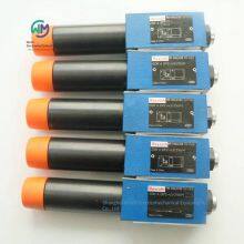
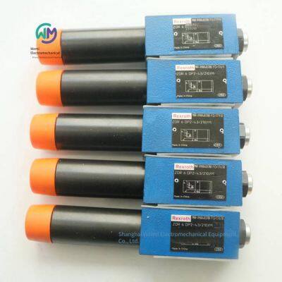
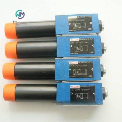
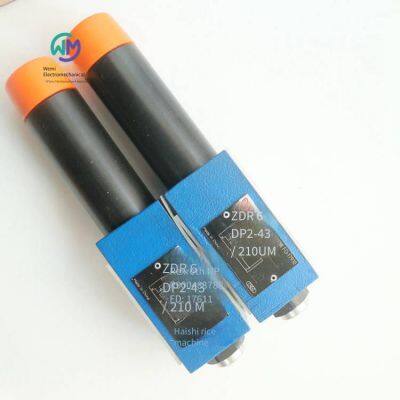
Rexroth Stacked Pressure Reducing Valve Zdr6dp2-43/210ym


Related Products
-
 Aventics Air Distribution Block R412006251US$ 32.31 - 33.85MOQ: 2 Pieces
 -
Aventics Pilot Valve 1827414004US$ 61.54 - 64.62MOQ: 1 Piece
-
Aventics Pilot Solenoid Valve 0493832506US$ 100 - 104.62MOQ: 1 Piece
-
Aventics Industrial Buffer 3702005000US$ 461.54 - 469.23MOQ: 1 Piece
-
Aventics 3/5-way Solenoid Valve 0820056601US$ 120 - 123.08MOQ: 1 Piece
REXROTH Stacked Pressure Reducing Valve ZDR6DP2-43/210YM, the main product of Shanghai Weimi Mechanical & Electrical Equipment Co., Ltd. Sales hotline: 13524123009; Contact person: Lei Qing; Product real-shot pictures, original genuine products, in-stock inventory, affordable prices; Warmly welcome new and old customers to consult and purchase!
Rexroth REXROTH Direct-acting Pressure Reducing Valve
ZDR6D
Specification 6
Component series 4X
Maximum working pressure 350 bar
Maximum flow rate 50 l/min
Stacked valve
Oil port mounting surface, conforming to ISO 440-03-02-0-05 (with or without holes)
4 pressure levels
4 optional adjustment types:
Knob
Hexagonal threaded pin and protective cap
Lockable knob with scale
Knob with scale
Pressure reduction in channels A, B or P
Check valve, optional (only for model “A”)
Anti-corrosion design
The ZDR type valve is a direct-acting pressure reducing valve with a stacked valve plate design, which can limit the pressure of the secondary oil circuit. It is used to reduce the system pressure.
The pressure reducing valve is mainly composed of a housing, a control spool, a compression spring, an adjustment type and an optional check valve.
The secondary pressure is set through the adjustment type.
Model “A”
The valve is in the open state in the initial position. The hydraulic oil can flow from channel A to channel A without restriction. At the same time, the pressure in channel A acts on the surface of the plunger opposite to the compression spring through the control oil circuit. If the pressure in channel A exceeds the value set at the compression spring, the control spool will be pushed away from the compression spring and move to the control position, so that the set pressure in channel A remains constant.
The control signal and pilot oil are provided from the inside of channel A2 through the control oil circuit.
When the pressure in channel A continues to increase due to the external force acting on the actuator, the pressure will force the control spool to move further away from the compression spring.
In this way, channel A will be connected to the oil tank via the control edge on the control spool and the housing. A large amount of hydraulic oil will flow back to the oil tank, so the pressure will no longer increase.
The leakage oil in the spring chamber is always discharged externally through the hole into channel T (Y).
The pressure gauge connection is used to control the secondary pressure of the valve.
The check valve can be used to achieve free backflow from channel A to A, but only for model “A”.
Models “P” and “B”
For model “P”, pressure reduction can be achieved in channel P. The control signal and pilot oil are provided from the inside of channel P.
For model "B", the pressure in channel P decreases, but the pilot oil can be obtained from channel B.
Precautions:
If the directional valve is in the spool position from P to A, the pressure in channel B shall not exceed the set secondary pressure. Otherwise, pressure reduction will occur in channel A.
Order numbers and models of REXROTH pressure reducing valves from Germany:
R900410813 ZDR6DA2-4X/75Y
R900410815 ZDR6DA2-4X/75YM
R900431771 ZDR6DB2-45/75YM
R900410806 ZDR6DP1-4X/150YM
R900483785 ZDR6DP2-4X/25YM
R900483786 ZDR6DP2-4X/75YM
R900483786 ZDR6DP2-43/75YM
R900483787 ZDR6DP2-4X/150YM
R900483787 ZDR6DP2-43/150YM
R900483788 ZDR6DP2-4X/210YM
R900483788 ZDR6DP2-43/210YM
R900400663 ZDR6DP2-4X/210YMV
R900473199 ZDR6DP3-4X/150YM
REXROTH direct-acting proportional relief valves without integrated electronic components (OBE)
R901000848 DBET-62/350G24K4V
DBET
Specification 6
Component series 6X
Maximum working pressure 420 bar
Maximum flow rate 2 l/min
The direct-acting valve is used to limit the system pressure.
Operated by a proportional electromagnet.
Proportional electromagnet with centering thread and detachable coil.
For subplate mounting: Hole pattern according to ISO 4401.
Modular amplifier in European board format and as a plug-in amplifier.
Individually adjustable up and down ramps, and the control value-pressure characteristic curve can be finely adjusted.
The DBET type proportional relief valve is a remote control valve with a seat design, which can be used to limit the system pressure. It is operated by a proportional electromagnet with a centering thread and a detachable coil. The inside of the coil is connected to port T or Y and filled with hydraulic oil. According to different electrical control values, these valves can be used to steplessly set the system pressure to be limited. The valve is mainly composed of a housing, a proportional electromagnet, a valve seat and a valve frame.
Basic principle
To set the system pressure, the control value needs to be set at the control electronic component. The electronic component drives the electromagnetic coil with current according to the control value. The proportional electromagnet converts the current into mechanical force, and the mechanical force acts on the valve spool through the armature plunger. The valve spool is pushed into the valve seat and blocks the connection between oil ports P and T or Y. If the hydraulic force on the valve spool is equal to the magnetic force of the coil, the valve controls the set pressure by lifting the valve spool away from the valve seat, allowing the hydraulic oil to flow from oil port P to T or Y. If the control value is zero, the control electronic component only applies a small control current to the proportional electromagnet, and a small set pressure is also set.
Rexroth Direct-acting proportional relief valve with integrated electronic components
DBETE
R901045246 DBETE-62/315G24K31F1V
R901121103 DBETE-62/420G24K31F1V
Specification 6
Component series 6X
Maximum working pressure 420 bar
Maximum flow rate 2 l/min
Direct-acting valve for limiting system pressure
Operated by a proportional electromagnet
Proportional electromagnet with centering thread and detachable coil
For subplate mounting: Hole pattern according to ISO 4401
Small manufacturing tolerance for the setpoint pressure characteristic curve
The DBETE type proportional relief valve is a remote control valve with a seat design and integrated electronic components, which can be used to limit the system pressure. It is operated by a proportional electromagnet with a centering thread and a detachable coil. The inside of the coil is connected to oil port T or Y and filled with hydraulic oil. Depending on the electrical control value, these valves can be used to steplessly set the system pressure to be limited. The valve is mainly composed of a housing, a proportional electromagnet, a valve seat, a valve spool, and integrated electronic components. The power supply voltage and control value voltage are applied to the connector. The setpoint pressure characteristic curve has been adjusted with very low manufacturing tolerances at the factory.
Basic principle
To set the system pressure, the control value needs to be set at the control electronic component. The electronic component drives the electromagnetic coil with current according to the control value. The proportional electromagnet converts the current into mechanical force, and the mechanical force acts on the valve spool through the armature plunger. The valve spool is pushed into the valve seat and blocks the connection between oil ports P and T or Y. If the hydraulic force on the valve spool is equal to the magnetic force of the coil, the valve controls the set pressure by lifting the valve spool away from the valve seat, allowing the hydraulic oil to flow from oil port P to T or Y. If the control value is zero, the control electronic component only applies a small control current to the proportional electromagnet, and a small set pressure is also set.
Rexroth Pilot-operated proportional pressure reducing valve
DRE, DREE
R900932943 DRE6-11/100MG24K4M
0811402055 DRE6X-11/175MG24-8NZ4M
Specification 6
Component series 1X
Maximum working pressure 210 bar
Maximum flow rate 30 l/min
Connection type: Base mounting
Oil port mounting surface: ISO 4401-03-02-0-05
Installation position: Any
Ambient temperature range: -20 … +70℃
Storage temperature range: -20 … +80℃
Protection class according to EN 60529 standard: IP65 (if a suitable and correctly installed connection plug is used.)
Compliance: CE checked according to EMC Directive 2014/30/EU, EN 61000-6-2 and EN 61000-6-3
Hydraulic oil temperature range: -20 … +80℃
Viscosity range: 15 … 380mm²/s
Maximum allowable contamination level of hydraulic oil, cleanliness class according to ISO 4406 (c): Class 20/18/15
Pilot flow rate: 0.65l/min
Maximum flow rate: 30l/min
Mineral oil: HL, HLP
Suitable sealing materials: NBR, FKM
Hysteresis: ± 2.5%
Repeatability:
Linearity: ± 3.5%
Manufacturing tolerance of the control value pressure characteristic curve: ± 2-3%
Step response: ≈ 150ms
Power supply: 24VDC
Minimum control current: 100mA
Maximum control current: 1600mA
Resistance of the electromagnetic coil
Low temperature value at 20 °C: 5Ω
Maximum high temperature value: 7.5Ω
Duty cycle: 100%
Current consumption: 1.5A
External fuse device: 2A. Time delay
Input
Voltage: 0 … 10V
Current 4 … 20mA
Used for pressure reduction in port A (with pressure limiting device)
Operated by a proportional solenoid
For base plate mounting
The oil port mounting surface conforms to ISO 4401-03-02-0-05
When operating with external control electronics, with electrical adjustment, the manufacturing tolerance of the setpoint pressure characteristic curve is small
Small set pressure in port A
With integrated electronics (OBE), optional
CE standard compliant with EMC Directive 2014/30/EU
The DRE(E) type valve is an electronically controlled pilot-operated three-way pressure reducing valve, which can provide pressure limitation for the electrical appliance. This valve is used to reduce the system pressure.
This valve basically consists of a pilot control valve, a proportional magnet, and a main valve with a main control spool.
Model DRE
Adjust the pressure to be reduced in channel A according to the rated value through the proportional magnet.
When using the relieved port P, the spring keeps the main control spool in the initial position.
Thereby opening the connection from A to T and blocking the connection from P to A.
Pressure connection from port P to the annular channel.
The pilot oil flows from the orifice to port T, through the flow regulator and the nozzle to the pilot control valve, and through the throttle gap to the longitudinal groove and the orifice.
Pressure reduction
The formation of the pilot pressure in the control chamber as a function of the setpoint.
Move the main control spool to the right, and the hydraulic oil flows from P to A.
The electrical appliance pressure is formed in port A of the spring chamber through the channel and the nozzle.
Increase the pressure in port A to the set pressure of the pilot control valve, which will cause the main control spool to move to the left. The pressure in port A is approximately the same as the set pressure of the pilot control valve.
Pressure limitation
If the pressure in port A exceeds the set pressure of the pilot control valve, the main control spool continues to move to the left.
Thereby disconnecting the connection from A to T and limiting the pressure generated in port A to the set setpoint.
Model DREE – With integrated electronics (OBE)
These valves are functionally and structurally in line with the DRE type. A housing with control electronics is also installed on the proportional magnet.
Connect the power supply voltage and the setpoint voltage or setpoint current through the device plug.
Fine-tune the setpoint pressure characteristic curve with a small sample deviation at the factory.
Rexroth REXROTH Pilot-operated Proportional Pressure Reducing Valve
DRE(M) 10, DRE(M) 20
R901279577 DREM10-61/200YG24-8K4M
Specifications: 10, 25
Component series: 6X
Maximum working pressure: 315 bar
Maximum flow rate: 300 l/min
Installation position: Any
Weight: 4.7kg, 6kg
Storage temperature range: -20 … +80℃
Ambient temperature range: -20 … +70℃
Pilot flow rate: 0.8l/min
Maximum flow rate: 200l/min, 300l/min
Hydraulic oil temperature range: -20 … +80℃
Viscosity range: 15 … 380mm²/s
Maximum allowable contamination level of hydraulic oil, cleanliness level in accordance with ISO 4406 (c): Grade 20/18/15 in accordance with ISO 4406 (c)
Hysteresis: ± 3.5%
Repeatability:
Linearity: ± 2%
Manufacturing tolerance of the control value pressure characteristic curve: ± 3.5
Step response: 10 ... 90% ≈ 130ms
Features
Valve for reducing system pressure
Operated by a proportional solenoid
Proportional solenoid with rotatable and removable coil
For subplate mounting: Oil port mounting surface conforms to ISO 5781
Third oil passage from A to Y (φ 7.5 mm)
Linearized pressure/given value characteristic curve
Good transient response
Optional check valve can be installed between A and B
Optional maximum pressure limit
Valves of type DRE(M) belong to pilot-operated pressure reducing valves. These valves can be used to reduce the working pressure.
The basic composition of these valves is a pilot control valve with a proportional solenoid, a main valve with a main spool, and an optional check valve.
Model DRE...
The pressure in channel A can be set according to the control value by the proportional solenoid.
In the rest position – i.e., when there is no pressure in channel B – the spring holds the main spool in its initial position. The connection from channel B to channel A is closed. Thus, start-up jumps can be avoided.
The pressure applied in channel A acts on the surface of the main spool through the hole. The pilot oil flows from channel B through the hole to the constant current control. The constant current control keeps the pilot flow constant, regardless of the pressure drop between channels A and B. The pilot flow flows from
the constant current control into the spring chamber, passes through the holes and, flows into channel Y through the valve seat and returns therefrom. The required pressure in channel A is preset through the relevant amplifier. The proportional solenoid moves the valve frame towards the valve seat and limits the pressure in the spring chamber to the set value. If the pressure at channel A is lower than the preset control value, the higher pressure in the spring chamber will move the main spool to the right. The connection from B to A is opened. If the set pressure at A is reached, the forces at the main spool are balanced - the main spool is in the control position.
Pressure at the spool end face of channel A = Pressure at the spool end face of the spring chamber – Spring force
If in a vertical hydraulic oil column (e.g., the hydraulic cylinder piston in the cut-off position), to reduce the pressure at A (e.g.), a lower control value can be preset through the control electronics, so that a lower pressure value can be pre - selected, and this pressure value will immediately appear in the spring chamber. The higher pressure value at A acting on the surface of the main spool pushes the main spool towards the protection plug to the cut-off position. The connection from A to B is blocked, and the connection from A to Y is opened. The force at the spring currently acts in the opposite direction to the hydraulic force on the surface of the main spool. At this main spool position, the hydraulic oil can flow from channel A through the control edge to Y and enter the return flow.
When the pressure at A drops to the sum of the pressure in the spring chamber and the ∆p of the spring, the main spool will close the large control hole in the socket at the control edge from A to Y.
The remaining pressure difference relative to the new control value at A is about 10 bar. The current pressure can only be unloaded through the control hole. In this way, a good transient response can be achieved without pressure undershoot. To achieve free return flow from channel A to channel B, a check valve can be optionally installed. Part of the filling flow at channel A can also flow into the return flow through the opened control edge from A to Y of the main spool.
Model DREM...
To provide hydraulic protection and prevent an unallowable high electrical control current from appearing on the proportional solenoid, which causes excessive pressure at port A, a spring - loaded relief valve can be optionally installed to limit the maximum pressure. This maximum pressure limit is a preset value based on the relevant pressure level.
Rexroth REXROTH Pilot - operated Proportional Relief Valve
(Z)DBE 6, (Z)DBEE 6
R901335463 ZDBEE6VP2 - 21/315G24K31A1M
Specification 6
Component Series 2X
Maximum working pressure: 350 bar
Maximum flow rate: 30 l/min
Installation position: Any
Weight: 2.5kg
Storage temperature range: -20 … +80℃
Ambient temperature range: -20 … +70℃
Return pressure: Return pressure at port A, external pilot oil
Maximum flow rate: 30l/min
Hydraulic oil temperature range: -20 … +80℃
Viscosity range: 15 … 380mm²/s
Maximum allowable contamination level of hydraulic oil, cleanliness class according to ISO 4406 (c): Class 20/18/15 according to ISO 4406 (c)
Hysteresis: ± 3%
Repeatability:
Linearity: ± 3.5%
Manufacturing tolerance of the control value-pressure characteristic curve, related to the hysteresis characteristic curve and pressure increase
Hydraulic oil: HL, HLP
Suitable sealing materials: NBR/FKM
Maximum coil current: 1760mA
Electromagnetic coil resistance
Low-temperature value at 20 °C: 5.5Ω
Maximum high-temperature value: 8.05Ω
Duty cycle: 100%
Power supply: 24VDC
Features
Pilot-operated proportional valve for limiting system pressure, separating and relieving pressure to return to the tank
Operated by a proportional solenoid
Proportional solenoid with rotatable and removable coil
For subplate mounting or sandwich valve design: Port mounting surface complies with ISO 4401-03-02-05 and DIN24340
Both the valve and control electronics are from the same source
External control electronics for models DBE and ZDBE
Linearized pressure/given value characteristic curve
Models DBEE and ZDBEE with integrated electronics (OBE)
Small manufacturing tolerance of the set value-pressure characteristic curve
The pilot-operated proportional relief valves of type (Z)DBE are activated by a proportional solenoid. These valves can be used to limit the system pressure. Depending on the electrical control value, these valves can be used to steplessly set the system pressure to be limited. The basic structure of these valves consists of a pilot control stage and a main stage. The pilot control assembly consists of a proportional solenoid, a valve frame and a valve seat. The main stage consists of a housing and a main spool assembly. The proportional solenoid converts the current proportionally into mechanical force. An increase in current leads to a corresponding increase in the magnetic force of the coil. The system pressure can be set according to the control value by the proportional solenoid. The pressure applied by the system at channel P acts on the right side of the main spool assembly. At the same time, the system pressure acts on the spring-loaded side of the spool through the control oil circuit equipped with a nozzle. Through the valve seat of the pilot line, the pressure at the valve frame of the spring chamber can overcome the force of the proportional solenoid. When the pressure reaches the preset value, the valve frame will be lifted from the valve seat. At this time, the pilot oil (depending on the model) can drain oil outward through port A (Y) or drain oil to the internal tank, which also limits the pressure on the spring-loaded side of the main spool. If the system pressure continues to rise slowly, the high pressure on the right side of the spool will push the spool to the left to the control position from P to T. At the minimum control current (corresponding to the zero control value), the minimum set pressure will be set.
Attention!
Prevent the fuel tank pipeline from running under no-load. Under the corresponding installation conditions, a preload valve (with a preload pressure of approximately 1 bar) must be installed.
The (Z)DBEE type pilot-operated proportional relief valve is activated by a proportional electromagnet. This valve can be used to limit the system pressure. Depending on the electrical control value, these valves can be used to steplessly set the system pressure to be limited. The basic structure of these valves consists of a pilot control stage and a main stage. The pilot control assembly is composed of a proportional electromagnet, a valve frame, and a valve seat. The proportional electromagnet is also equipped with a housing with control electronics. The power supply voltage and the control value voltage are applied to the connector. The control value pressure characteristic curve has been adjusted according to very low manufacturing tolerances at the factory. The main stage is composed of a housing and a main spool assembly. The proportional electromagnet converts the current proportionally into mechanical force. An increase in current will lead to a corresponding increase in the magnetic force of the coil. The system pressure can be set according to the control value through the proportional electromagnet. The pressure applied by the system at the channel P acts on the right side of the main spool assembly. At the same time, the system pressure will act on the spring-loaded side of the spool through the control oil circuit equipped with a nozzle. Through the valve seat of the pilot pipeline, the pressure at the valve frame of the spring chamber can overcome the force of the proportional electromagnet. When the pressure reaches the preset value, the valve frame will be lifted from the valve seat. At this time, the pilot oil (depending on the model) can drain oil outward through the oil port A (Y) or drain oil to the internal fuel tank, which will also limit the pressure on the spring-loaded side of the main spool. If the system pressure continues to rise slowly, the high pressure on the right side of the spool will push the spool to the left to the control position from P to T. When the control current is small (corresponding to zero control value), a small set pressure will be set.
Attention!
Prevent the fuel tank pipeline from running under no-load. Under the corresponding installation conditions, a preload valve (with a preload pressure of approximately 1 bar) must be installed.
R901304331 DBE6-21/100G24K4M
Rexroth direct-acting directional spool valve with electromagnetic activation
WE 6...E
Size 6
Component series 6X
Maximum working pressure 350 bar
Maximum flow rate (DC) 80 l/min
Maximum flow rate (AC) 60 l/min
Three-position four-way, two-position four-way, or two-position three-way models
Oil port mounting surface, in accordance with ISO 4401-03-02-0-05 (with or without holes)
High-power coil, optional 90° rotation
Electrical connection as a single or centered connection
Optional auxiliary operating device
Optional spool position monitoring
When the voltage is > 50 VAC or > 75 VDC, CE compliance meets the Low Voltage Directive 2014/35/EU
The electromagnetic coil is an approved component with a UR mark, conforming to UL 906, version 1982, optional
Certified by CSA, optional
The directional valves of the WE model are solenoid-operated directional spool valves, and this valve can be used as an electromagnetic assembly. They are used to control the start, stop, and direction of the flow.
The basic composition of this directional valve is a housing, one or two electromagnets, a control spool, and a return spring.
In the de-energized state, the control spool is held in the middle position or the initial position by the return spring (except for version "O").
When the electromagnet in the hydraulic oil is energized, the control spool moves from its rest position to the desired terminal position. In this way, the desired fluid direction can be issued according to the selected symbol.
After the electromagnet is turned off, the control spool will be pushed back to the middle position or the initial position (except for valves with an "OF" device and valves without spring type "O").
For auxiliary operation, the valve can be manually switched without energizing the magnet.
The hydraulic system must be properly vented to ensure normal operation.
Without spring return "O" (only applicable to symbols A, C, and D)
This model is a directional valve with two switching positions and two electromagnets and without a device. Valves without spring return at the control spool have no definite initial position in the de-energized state.
Without spring return, with device "OF" (only applicable to symbols A, C, and D)
This model is a directional valve with two switching positions and two electromagnets and with a device. The control spool is fixed in the corresponding switching position by the device. Therefore, during operation, there is no need to apply current to the electromagnet, which helps with energy-saving operation.
Model "73...A12" (soft switching behavior)
The combination of the control spool and the electromagnetic coil reduces the number of commutation strokes that occur when the valve is opened or closed. Compared with the standard valve, the commutation stroke (measured as the acceleration value a) can be reduced by about 85%, depending on the model of the control spool (see "Acceleration value").
Note:
Pressure peaks in the drain lines connecting two or more valves may cause unexpected movement of the control spool in models with a device. It is recommended to lay a separate return line or install a check valve in the drain line.
Due to the design principle, internal leakage will occur in the valve, and the leakage amount will increase during the service life.
Throttle plug-in
According to the main working conditions, if the flow rate may exceed the performance limit of the valve during the switching process, a throttle plug-in will be required.
Order numbers and models of German Rexroth solenoid valves:
R900561180 3WE6A62/EG24N9K4
R978017740 3WE6A6X/EG24N9K4/62
R900907814 3WE6B9-62/EG24N9K4
R900561272 4WE6C62/EG24N9K4
R900901748 4WE6C62/EW110N9K4
R900908879 4WE6D62/EG110N9K4
R900561274 4WE6D62/EG24N9K4
R900908590 4WE6D62/EG24N9K4/B12
R900903081 4WE6D62/EG205N9K4
R900916984 4WE6D62/EG220N9K4
R901008688 4WE6D62/EG220N9K4/V
R900909559 4WE6D62/EW230N9K4
R901483086 4WE6D62/OFEG110N9K4/B12
R900567512 4WE6D62/OFEG24N9K4
R900903465 4WE6D62/OFEG24N9K4/V
R900922533 4WE6FB62/EG24N9K4
R900567997 4WE6J73-62/EG24N9K4/A12
R900931967 4WE6JA62/EG24N9K4/B08
R900903463 4WE6L62/EG24N9K4/V
R900577475 4WE6M62/EG24N9K4
R900571012 4WE6R62/EG24N9K4
R900905896 4WE6Y62/EW110N9K4
R900556472 4WE6Y62/EG24K4QMAG24
R900561276 4WE6Y62/EG24N9K4
R900909178 4WE6Y62/EG24N9K4/B08
R900917497 4WE6Y62/EG24N9K4/B10
R900922335 4WE6Y62/EG220N9K4
R900765505 4WE6Y62/EG26N2K4K
R901073870 3WE6A62/OFEG220N9K4
R901235381 4WE6D46-62/OFEG24N9K72LSO407
R900561274 4WE6D6X/EG24N9K4
R900574632 4WE6D62/EG24K4QMBG24
R900909559 4WE6D6X/EW230N9K4
R900546257 4WE6D73-62/EG24N9K4/A12
R901235374 4WE6D73-6X/EG24N9K72L/A12
R900927437 4WE6D73-62/EG24N9K4/A12B10
R900561278 4WE6E62/EG24N9K4
R900903464 4WE6E62/EG24N9K4/V
R900921477 4WE6E62/EG24N9K4/B10
R900558641 4WE6E62/EW110N9K4
R901259406 4WE6E73-62/EG24N9K72L/A12=AN
R900561280 4WE6EA62/EG24N9K4
R901162080 4WE6EB62/EG220N9K4
R901034409 4WE6E6X/BG24NXDZ2/V
R900551703 4WE6J62/EW110N9K4
R900908878 4WE6J62/EG110N9K4
R900561288 4WE6J62/EG24N9K4
R900911762 4WE6J62/EW230N9K4
R900912079 4WE6J62/EW230N9K4/B10
R900548772 4WE6J62/EG24N9K4/V
R900922207 4WE6J62/EG220N9K4
R901235012 4WE6J62/EG24N9K72L
R900548271 4WE6J6X/EG24N9K4/B10
R900765511 4WE6J62/EG26N2K4K
R900561291 4WE6JB62/EG24N9K4
R900932917 4WE6JB62/EG24N9K4/V
R900561292 4WE6Q6X/EG24N9K4
R901235370 4WE6Q62/EG24N9K72L
R900940418 4WE6Y11-62/EG24N9K4
R900561286 4WE6H62/EG24N9K4
R900549534 4WE6HA62/EG24N9K4
R900561282 4WE6G62/EG24N9K4
R900912493 4WE6G62/EW230N9K4
R900561284 4WE6GA62/EG24N9K4
R900549534 4WE6HA62/EG24N9K4
R900578186 4WE6UA62/EG24N9K4
R901396248 4WE6U62/EG220N9K4/V
Rexroth Direct-acting Directional Spool Valves with Electromagnetic Actuation
WE 6...H
Size 6
Component Series 7X
Maximum Working Pressure 315 bar
Maximum Flow Rate 60 l/min
Three-position four-way, two-position four-way or two-position three-way models
Standard models
Oil port mounting surface complies with DIN 24340, Form A
DC coils with wet feet
Electromagnetic coils are rotatable
There is no need to open the pressure-tight sealed cavity when replacing the coil.
Electrical connection as a single connection
Implicit manual emergency operation
The directional valves of the WE model are directional spool valves operated by electromagnetic coils. These valves control the start, stop and direction of the fluid.
These directional valves are mainly composed of a housing, one or two coils, a control spool and one or two return springs. In the case of power failure, the control spool is fixed in the center position or the initial position by the return spring. The control spool is actuated by a coil with wet feet.
To ensure normal operation, please make sure to fill the pressure chamber of the coil with hydraulic oil!
The force of the coil acts on the control spool through the push rod and pushes the latter from its rest position to the required terminal position. In this way, the required flow direction can be released according to the symbol. After the coil is demagnetized, the return spring pushes the control spool back to its rest position.
The manual emergency operation can control the spool when the coil is not energized.
Order numbers and models of Rexroth solenoid valves from Germany:
R901089245 4WE6C70/HG24N9K4
R901087088 4WE6D70/HG24N9K4
R901087087 4WE6E70/HG24N9K4
R901108990 4WE6J70/HG24N9K4/B10
R901133322 4WE6HA70/HG24N9K4
R901089241 4WE6J70/HG24N9K4
R901108990 4WE6J70/HG24N9K4/B10
R901108705 4WE6JB70/HG24N9K4
REXROTH Stacked Pressure Reducing Valve ZDR6DP2-43/210YM

Send Inquiry to This Supplier

You May Also Like
-
Aventics Precision Oil Mist Separator 0821301411US$ 73.85 - 76.92MOQ: 1 Piece
-
Aventics 2/3-way Solenoid Valve 0820019967US$ 36.92 - 43.08MOQ: 5 Pieces
-
Aventics Explosion-proof Coil for Solenoid Valve 1827414303US$ 141.54 - 146.15MOQ: 1 Piece
-
Aventics Valve Island Solenoid Valve 0820056051US$ 89.23 - 92.31MOQ: 1 Piece
-
Main Engine Ahead Starting Control Solenoid Valve 3723522220US$ 384.62 - 396.92MOQ: 1 Piece
-
Rexroth Dc220v Solenoid Valve 4we10d33/cg220n9k4/vUS$ 438.46 - 446.15MOQ: 1 Piece
-
Aventics Air Source Shut - off Valve 0821300913US$ 53.85 - 55.38MOQ: 1 Piece
-
Rexroth Proportional Relief Valve 0811402016 Dbetx-10/315g24-8nz4mUS$ 369.23 - 384.62MOQ: 1 Piece
-
Duplomatic Gear Pump Gp20140r95b20nUS$ 353.85 - 369.23MOQ: 1 Unit
-
Rexroth Proportional Cartridge Valve 0811402622 Fesxe40ca-1x/500lk0b1mUS$ 2769.23 - 2846.15MOQ: 1 Piece


