

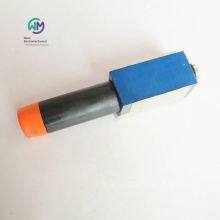
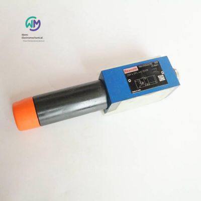
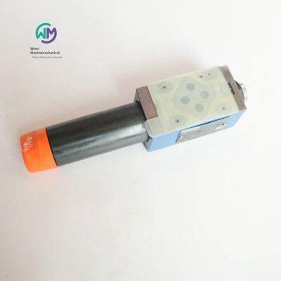
Rexroth Pressure Reducing Valve Zdr6dp2-4x/25ym


Related Products
-
 Rexroth Stacked Pressure Reducing Valve Zdr6dp2-43/210ymUS$ 104.62 - 107.69MOQ: 1 Piece
 -
Aventics Air Distribution Block R412006251US$ 32.31 - 33.85MOQ: 2 Pieces
-
Aventics Pilot Valve 1827414004US$ 61.54 - 64.62MOQ: 1 Piece
-
Aventics Pilot Solenoid Valve 0493832506US$ 100 - 104.62MOQ: 1 Piece
-
Aventics Industrial Buffer 3702005000US$ 461.54 - 469.23MOQ: 1 Piece
REXROTH Pressure Reducing Valve ZDR6DP2-4X/25YM, the main product of Shanghai Weimi Mechanical & Electrical Equipment Co., Ltd. Sales hotline: 13524123009; Contact person: Lei Qing; Real product photos, original and genuine products, in-stock inventory, affordable prices; We sincerely welcome new and old customers to consult and purchase!
Rexroth REXROTH Direct-acting Pressure Reducing Valve
ZDR6D
Specification 6
Component series 4X
Maximum working pressure 350 bar
Maximum flow rate 50 l/min
Stack valve
Oil port mounting surface, conforming to ISO 440-03-02-0-05 (with or without holes)
4 pressure levels
4 optional adjustment types:
Knob
Hexagonal threaded pin and protective cap
Lockable knob with scale
Knob with scale
Pressure reduction in channels A, B or P
Check valve, optional (only for model "A")
Anti-corrosion design
The ZDR type valve is a direct-acting pressure reducing valve with a stack valve plate design, which can limit the pressure of the secondary oil circuit. It is used to reduce the system pressure.
The pressure reducing valve is mainly composed of a housing, a control spool, a compression spring, an adjustment type and an optional check valve.
The secondary pressure is set through the adjustment type.
Model "A"
The valve is open in the initial position. Hydraulic oil can flow from channel A to channel A without restriction. At the same time, the pressure in channel A acts on the plunger surface opposite to the compression spring through the control oil circuit. If the pressure in channel A exceeds the value set at the compression spring, the control spool will be pushed away from the compression spring and move to the control position, so that the set pressure in channel A remains constant.
The control signal and pilot oil are provided from the inside of channel A2 through the control oil circuit.
When the pressure in channel A continues to increase due to the external force acting on the actuator, the pressure will force the control spool to move further away from the compression spring.
In this way, channel A will be connected to the oil tank via the control edge on the control spool and the housing. A large amount of hydraulic oil will flow back to the oil tank, so the pressure will no longer increase.
The leakage oil in the spring chamber is always externally discharged into channel T (Y) through the hole.
The pressure gauge connection is used to control the secondary pressure of the valve.
The check valve can be used to achieve free backflow from channel A to A, but only for model "A".
Models "P" and "B"
For model "P", pressure reduction can be achieved within channel P. By providing control signals and pilot oil from inside channel P.
For model "B", the pressure in channel P is reduced, but the pilot oil can be obtained from channel B.
Precautions:
If the directional valve is in the spool position from P to A, the pressure in channel B shall not exceed the set secondary pressure. Otherwise, pressure reduction will occur in channel A.
Order numbers and models of REXROTH pressure reducing valves from Germany:
R900410813 ZDR6DA2-4X/75Y
R900410815 ZDR6DA2-4X/75YM
R900431771 ZDR6DB2-45/75YM
R900410806 ZDR6DP1-4X/150YM
R900483785 ZDR6DP2-4X/25YM
R900483787 ZDR6DP2-4X/150YM
R900483787 ZDR6DP2-43/150YM
R900483788 ZDR6DP2-4X/210YM
R900483788 ZDR6DP2-43/210YM
R900400663 ZDR6DP2-4X/210YMV
R900473199 ZDR6DP3-4X/150YM
REXROTH pilot-operated pressure reducing valves
DR
Size 10 … 25
Component series 1X; 4X
Maximum working pressure 315 bar
For subplate mounting
Hole pattern according to ISO 5781
For threaded connection
As an insert valve
4 optional adjustment types:
Knob
Hexagon socket and protective cap
Lockable knob with scale
Knob with scale
4 pressure levels
The DR type pressure valve is a pilot-operated pressure reducing valve. It is used to reduce the system pressure.
It mainly consists of a screw-in insert valve (cartridge) and a housing, and can be selected with or without a check valve (only for subplate mounting).
The valve is open in the rest position. The hydraulic oil can flow freely from the inlet channel to the outlet channel through the main control spool. The pressure in the outlet channel is applied to the spring-loaded side of the main control spool through a hole. At the same time, the pressure acts on the side of the main control spool opposite to the spring through holes and orifices.
If the pressure in the outlet channel exceeds the value set on the spring, the pilot seat opens.
Hydraulic oil flows from the spring-loaded side of the main control spool into the spring chamber through the nozzle and the pilot seat.
The main control spool moves to the control position and keeps the pressure of the outlet passage set by the spring constant. The return oil of the pilot oil from the spring chamber is always realized externally through the Y port.
For the base plate installation of model "P", a check valve can be optionally installed to achieve free backflow from passage A to passage B.
Rexroth REXROTH Pilot-operated Pressure Reducing Valve
Z3DR10
Size 10
Component series 1X
Maximum working pressure 350 bar
Maximum flow rate 120 l/min
Stack valve
The port mounting surface complies with ISO 4401-05-04-0-05 (standard model) or ISO 4401-05-05-0-05 (model "SO30").
4 pressure levels are optional.
2 adjustment types are optional:
Hexagon socket spindle and protective cap
Lockable knob with scale
Anti-corrosion design
The Z3DR type valve is a pilot-operated three-way pressure reducing valve with a stack valve plate design, which can limit the pressure of the actuator. Such valves can be used to reduce and control the system pressure.
Such valves are mainly composed of a pilot control valve and a housing including the main stage part. The secondary pressure is set through the adjustment type.
The Rexroth pilot-operated pressure reducing valve is characterized by high stability and low hysteresis.
With model "MS", the set secondary pressure can be measured and monitored through the pressure load cell at the measurement port (please refer to "Dimensions").
If the secondary pressure at the actuator port P (A, B) further rises beyond the set value, the valve will open the third pipeline of the return port TA (TB). This can prevent an unacceptable pressure rise in the actuator passage.
Order numbers and models of Rexroth REXROTH pressure reducing valves:
R901435208 Z3DR10VA2-10/200V
R901160168 Z3DR6VP2-10/200MSV
R901418087 Z3DR6VP3-10/315V
Rexroth REXROTH Double One-way Throttle Valve
Z2FS6
Size 6
Component series 4X
Maximum working pressure 315 bar
Maximum flow rate 80 l/min
Stack valves
The oil port mounting surface complies with DIN 24340, Type A
The oil port mounting surface complies with ISO 4401-03-02-0-05 (with holes)
Used to limit the main oil flow or pilot oil flow at the oil ports of 2 actuators.
4 adjustment types:
Adjusting screw with lock nut and protective cap
Lockable knob with scale, Hexagon socket spindle with scale, Knob with scale
Used for oil supply or return oil throttling
The Z2FS6 valve is a double one-way throttle valve designed with a stack valve plate. It is used to limit the main oil flow or pilot flow at the oil ports of one or two actuators.
Two one-way throttle valves arranged symmetrically to each other can limit the flow in one direction while allowing free backflow in the opposite direction.
If it is oil supply throttling, the hydraulic oil will pass through the throttling point formed by the valve seat and the throttle valve core and enter the actuator A2 through the passage A1. The throttle valve core can be axially adjusted by the adjusting screw, thus allowing the adjustment of the throttling point.
The hydraulic oil flowing back from the actuator A2 moves the valve seat relative to the spring along the direction of the throttle valve core, so that the hydraulic oil can flow through the one-way valve unobstructed. Depending on the installation position, the throttling effect may occur in the oil supply or discharge.
Main flow restriction (Model "2Q")
To adjust the speed of the actuator (main flow restriction), a double one-way throttle valve should be installed between the directional valve and the base plate.
Pilot flow restriction (Model "1Q")
Through the pilot-operated directional valve, the double one-way throttle valve can be used to adjust the switching time (pilot flow restriction). In this case, the valve is installed between the pilot control valve and the main valve.
Order numbers and models of German Rexroth throttle valves:
R900481621 Z2FS6-2-4X/1Q
R900481624 Z2FS6-2-4X/2QV
R900481624 Z2FS6-2-46/2QV
R900476838 Z2FS6-5-4X/2QV
Rexroth one-way throttle valve
Z2FS10
Specification 10
Component series 3X
Maximum working pressure 315 bar
Maximum flow rate 160 l/min
Stack valves
The oil port mounting surface complies with ISO 4401-05-04-0-05
Used to limit the main oil flow or pilot oil flow at the oil ports of 2 actuators.
3 adjustment types:
Lockable knob with scale, Hexagon socket spindle with scale, Knob with scale
Oil inlet or return oil throttling
Anti-corrosion design
The Z2FS 10 valve is a one-way throttle valve with a stacked valve plate design. It is used to limit the main oil flow or pilot flow at one or two actuator ports.
Two one-way throttle valves arranged symmetrically to each other can limit the flow in one direction while allowing free backflow in the opposite direction.
If it is oil supply throttling, the hydraulic oil will pass through the throttling point formed by the control edge and the throttle valve spool and be introduced into the actuator A2 through the passage A1. The throttle valve spool can be axially adjusted through the main shaft, thus allowing the adjustment of the throttling point.
At the same time, the hydraulic oil in the passage A1 is introduced to the piston side through the hole. The active pressure and spring force keep the throttle valve spool in the throttling position.
The hydraulic oil flowing back from the actuator B2 moves the throttle valve spool in the direction opposite to the spring, allowing the hydraulic oil to flow unobstructed through the one-way valve. Depending on the installation position, the throttling effect may occur in the oil supply or discharge.
Main flow restriction
To adjust the speed of the actuator (main flow restriction), a one-way throttle valve should be installed between the directional valve and the base plate.
Pilot flow restriction
Through the pilot-operated directional valve, a one-way throttle valve can be used to adjust the switching time (pilot flow restriction). In this case, the valve is installed between the pilot control valve and the main valve.
Order numbers and models of German Rexroth throttling valves:
R900517812 Z2FS10-5-3X/V
Rexroth one-way throttle valve
Z2FS16
Specification 16
Component series 3X
Maximum working pressure 350 bar
Maximum flow rate 250 l/min
Stacked valve
The port mounting surface complies with ISO 4401-07-07-0-05
Limit the flow at 2 actuator ports
Adjustment method: Adjusting rod with hexagon socket hole
Oil inlet or return oil throttling
The Z2FS16 valve is a one-way throttle valve with a stacked valve plate design. It is used to limit the flow at one or two actuator ports.
Two one-way throttle valves arranged symmetrically can limit the flow in one direction (through the adjustable throttle valve spool) while allowing free backflow in the opposite direction.
If it is oil supply throttling, the hydraulic oil will pass through the throttling point and be introduced into the actuator A2 through the passage A1. The throttle valve spool can be axially adjusted through the main shaft, thus allowing the adjustment of the throttling point.
At the same time, the hydraulic oil in the passage A1 is introduced to the piston side through the hole.
The active pressure and spring force keep the throttle valve spool in the throttling position.
The hydraulic oil flowing back from actuator B2 moves the throttle valve spool, allowing the hydraulic oil to flow unimpeded through the check valve. Depending on the model ("S" or "S2"), the throttling effect may occur during oil supply or discharge.
Flow restriction
To adjust the speed of the actuator, a one-way throttle valve should be installed between the directional valve and the base plate.
Order numbers and models of German Rexroth throttle valves:
R900459203 Z2FS16-8-31/S
R900457256 Z2FS16-8-31/S2
Rexroth one-way throttle valve
Z2FS22
Specification 25
Component series 3X
Maximum working pressure 350 bar
Maximum flow rate 360 l/min
Stacked valve
The oil port mounting surface complies with ISO 4401-08-08-0-05
Used for restricting the main flow or control flow of one or two actuator interfaces
Adjustment method: The adjustment lever has an Allen socket
Used for oil supply or return oil throttling
Anti-corrosion design
The Z2FS22 valve is a one-way throttle valve with a stacked valve plate design. It is used to restrict the flow at one or two actuator ports.
Two symmetrically arranged one-way throttle valves can restrict the flow in one direction (through the adjustable throttle valve spool) while allowing free backflow in the opposite direction.
If it is oil supply throttling, the hydraulic oil will pass through the throttle point and be led into actuator A2 through passage A1. The throttle valve spool can be axially adjusted through the main shaft, allowing adjustment of the throttle point.
At the same time, the hydraulic oil in passage A1 is led to the piston side through the hole. The active pressure and spring force keep the throttle valve spool in the throttling position.
The hydraulic oil flowing back from actuator B2 moves the throttle valve spool, allowing the hydraulic oil to flow unimpeded through the check valve. Depending on the model ("S" or "S2"), the throttling effect may occur during oil supply or discharge.
Flow restriction
To adjust the speed of the actuator, a one-way throttle valve should be installed between the directional valve and the base plate.
Order numbers and models of German Rexroth throttle valves:
R900443176 Z2FS22-8-31/S2
Rexroth two-way flow control valve
2FRM6B
Specification 6 mm diameter
Weight 1.3 kg
Installation location Anywhere
Component series 3X
High flow rate 32 l/min
Ambient temperature range -20 … +50℃
Maximum working pressure 315bar
Minimum pressure difference 6 … 14bar
Hydraulic oil temperature range -20 … +80℃
Viscosity range 10 … 800mm²/s
The oil port mounting surface conforms to DIN 24340 Form A
Base plate (to be ordered separately)
Check valve, optional
2 adjustment types, optional:
- With graduated knob
- With graduated and lockable knob
General information
The 2FRM type flow control valve is a two-way flow control valve.
It is used to keep the flow rate stable, regardless of pressure and temperature.
The basic structure of this valve consists of a housing, a knob, a throttle orifice bushing, a pressure compensator and an optional check valve.
2FRM 6 B…MV
Type flow control valve (without external closing, without check valve)
The flow from port A to port B is throttled at the throttle point. The throttle profile is set by turning the knob. To ensure that the flow rate at port B remains stable regardless of pressure, a pressure compensator is installed downstream of the throttle point.
When there is no flow through the valve, the compression spring presses the pressure compensator down to its stop point, keeping the pressure compensator in the open position. When hydraulic oil flows through the valve, the pressure acting on port A exerts a force on the pressure compensator through the throttle orifice.
The pressure compensator will move to the control position until the forces are balanced. When the pressure at port A rises, the pressure compensator will move in the closing direction until the forces are balanced again. It is this continuous compensation action of the pressure compensator that provides the system with a stable flow rate.
In order to control the flow rate in two directions through the valve, a Z4S 6 type rectifier stacking valve plate can be installed under this flow control valve.
Order numbers and models of REXROTH flow control valves from Germany:
R900205577 2FRM6B36-3X/0,2QMV
R900205509 2FRM6B36-3X/10QRV
R900205514 2FRM6B36-3X/32QMV
R900209927 2FRM6B76-34/10QRV
Rexroth Two-way Flow Control Valve
2FRM
Component Series 3X
Specifications: 10mm Diameter, 16mm Diameter
Weight: 5.6kg, 11.3kg
Temperature Range: -20 … +80°C
Maximum Working Pressure: 315 bar
Minimum Pressure Difference: 3 … 7bar, 5 … 12bar
Maximum Flow Rate: 160 l/min
Viscosity Range: 10 … 800mm²/s
For Base Plate Installation
Oil Port Mounting Surface Complies with DIN 24340 Form G and ISO 6263
Mechanical Actuation
Pressure Compensator Stroke Limit, Optional
Startup Jump Reduction
Speed Regulation in Both Directions via Flow Direction Adjustment Plate
The 2FRM type flow control valve is a two-way flow control valve. They are used to maintain a stable flow rate, generally unaffected by pressure and temperature.
Generally, the valve consists of a housing, a throttle orifice bushing, a pressure compensator with optional stroke limit, a check valve, an adjustment element in model 2FRM, a gear piston drive, and a directional valve. The flow from port A to port B is throttled at the throttle point. In model 2FRM, the throttle profile can be set by mechanically rotating the curve bolt on the adjustment element. The rate can be set via a one-way throttle valve. To fix the required adjustment range, adjustable stroke limits are provided on both sides of the gear piston drive. An upstream pressure compensator is included to ensure that the flow rate at the throttle point is unaffected by pressure and remains stable.
Since the throttle point uses an orifice design, it is not affected by temperature.
Free backflow from port B to port A is achieved through the check valve.
Flow adjustment can only be from port A to port B.
To control the flow rate in both directions, a Z4S type rectifier stacking valve plate can be installed under the flow control valve.
Order Numbers and Models of Rexroth Flow Control Valves:
R900423261 2FRM10-31/50LB
R900423261 2FRM10-3X/50LB
R900424902 2FRM16-32/160LB
Rexroth Diaphragm Accumulator
HAD
Component series 1X and 2X
Nominal capacity 0.075 … 3.5 l
Maximum working pressure 250 bar
Integral structure Diaphragm accumulator
Installation position Any, preferably the hydraulic oil connector socket at the bottom
Installation type Using a clamp or welding through a pipe joint
Temperature range -15 … +65℃
Pipeline connection Internal thread
Hydraulic oil Hydraulic oil complying with DIN 51524
One of the main tasks of a hydraulic accumulator is to receive a certain amount of pressurized liquid from the hydraulic system and return it to the system when needed.
When the liquid is pressurized, the treatment of the hydraulic accumulator is similar to that of a pressure vessel, and it must be designed for its maximum working overpressure considering the acceptance standards of the installation country or region.
In most hydraulic systems, hydraulic/pneumatic (inflatable) accumulators with separating elements are used.
The difference between bladder accumulators, piston accumulators and diaphragm accumulators lies in the type of separating element.
A hydraulic accumulator basically consists of a hydraulic oil part, a gas part and an airtight separating element. The hydraulic oil part is connected to the hydraulic oil circuit. When the pressure increases, the gas is compressed and the liquid enters the hydraulic accumulator. When the pressure drops, the compressed gas expands and discharges the accumulated hydraulic oil into the oil circuit.
Diaphragm accumulator
A diaphragm accumulator includes a steel pressure-resistant container, which is usually spherical or cylindrical. There is a separating element inside the accumulator, that is, a film made of elastic and flexible material (elastic material), with a closing button and a protective plug. They comply with Directive 97/23/EC.
Applications
There are various applications for hydraulic/pneumatic accumulators:
Energy storage to save pump drive power in intermittent operating systems.
Energy reserve for emergencies, such as when the hydraulic pump fails.
Compensation for leakage losses.
Absorption of shocks and vibrations during periodic vibrations.
Volume compensation during pressure and temperature changes.
Elements of the vehicle suspension system.
Absorption of mechanical shocks.
Working mode
Hydraulic oil is almost incompressible, so it cannot store pressure energy. Rexroth hydraulic/pneumatic accumulators use the compressibility of gas to store hydraulic oil. Only inert gases can be used. Usually, "nitrogen" of grade 4.0 is used.
Installation conditions
Inflation pressure
Diaphragm accumulators are usually delivered in a ready-to-run state. The charging pressure (p0) is engraved on the accumulator shell.
Inflation
Hydropneumatic accumulators can only be filled with Grade 4.0 nitrogen, with a pure nitrogen content of 99.99 vol.%.
Permissible operating temperature
In the "standard version", Rexroth gas-oil accumulators are suitable for -15 to +80°C.
Installation position
Diaphragm accumulators can be installed in any installation position.
Above the gas valve, a 200 mm installation space must be provided for the test and charging device.
Installation
When installing the accumulator, ensure that possible forces, such as those generated by vibrations or accelerations specific to the application, are safely absorbed. When using multiple installation points, stresses caused by operation, elastic deformation, or temperature expansion should be avoided.
Important notes
Intended use
Rexroth diaphragm accumulators -1X/2X are used to set up hydraulic drive systems in stationary mechanical engineering and plant construction.
The diaphragm accumulator must be securely fixed to the machine or system using installation elements. The fastening is designed to keep the oil port tension-free. In particular, no tension or static or dynamic inertial forces should be applied to the oil port.
When selecting a suitable installation point, the thermal expansion of the support structure and vibrations from the environment should be considered.
Safety instructions for gas-oil accumulators
The end-user of the machine needs to attach the operating instructions RE 50150-B for the machine or system and the CE conformity declaration for containers larger than 1 liter.
General information on hydropneumatic accumulators in hydraulic systems can be found in DIN EN ISO 4413.
Safety equipment
Notes:
According to the Pressure Equipment Directive 2014/68/EU, it must be ensured that the hydropneumatic accumulator does not operate outside the permitted range.
In order not to exceed the maximum working pressure, according to data sheet 50131, Bosch Rexroth recommends using the ABZSS type accumulator cut-off block.
Order numbers and models of German Rexroth REXROTH accumulators:
0531602573 HAD0,7-180-1X/50G04A-1N111-BA
Rexroth REXROTH pilot-operated pressure cut-off valve
DA6V
Specification 6
Component series 5X
Maximum working pressure 350 bar
Maximum flow rate 40 l/min
Weight 2.2kg
Installation position Any
Temperature range -30 … +80℃
Viscosity range 10 … 800mm²/s
Recommended viscosity range: 20 … 60mm²/s
For base plate installation
The oil port mounting surface conforms to ISO 5781-03-04-0-00 (non-standard and without holes)
Base plate (to be ordered separately)
As a cartridge valve
Adjustment type: Hexagon socket and protective cap
4 pressure levels
Adjustable switching pressure difference (10% to 50% of the nominal value)
The DA6V type pressure valve is a pilot-operated pressure cut-off valve with steplessly adjustable switching pressure difference. This type of valve is mainly composed of the pilot control stage and main stage of the screw-in cartridge valve, a check valve, and a housing.
The pump flow in P is introduced into the accumulator of the system through port B. If the pressure of the actuator in port B exceeds the set top switching pressure, the pilot control valve will open and start the pilot oil discharge through port A (Y). The check valve will close the connection from port B to P, and the pump flow will be switched to the pressure relief oil circuit (from P to T).
Model DA6VP
Switch the pump flow from P to B (pump → actuator) to P to T (pump → oil tank).
The pump supplies oil to the hydraulic system (from P to B) through the check valve. The pressure in channel B acts on the pilot control of the screw-in cartridge valve through the control oil circuit and orifice. At the same time, the pressure in channel P is applied to the spring-loaded side of the main control spool through the orifice. When the top cut-off pressure set by adjusting the spindle in the screw-in cartridge valve reaches the hydraulic system (channel B), the pilot control of the screw-in cartridge valve will open the connection from the spring-loaded side of the main spool to the control oil circuit and the external connection to the oil tank through port A (Y). Due to the presence of the orifice, a pressure drop is generated at the main spool. The main spool will lift off the valve seat, opening the connection from P to T. The check valve closes the connection from B to P, and the pilot control of the screw-in cartridge valve remains in the open position under the action of the actuator pressure in B.
Switch the pump flow from P to T (pump → oil tank) to P to B (pump → actuator).
If the actuator pressure in B decreases compared with the cut-off pressure according to the lower bottom pressure value set at the adjusting spindle, the pilot control of the screw-in cartridge valve will be set back to its initial position.
In this way, the pressure accumulates on the spring-loaded side of the main spool. Thus, the connection from P to T is closed by the spring, and the pump supplies oil to the hydraulic system through the check valve, that is, from P to B.
Model DA6VA
In this valve model, the pump pressure port is not designed in P but in A. The valve directs the pump flow from A to P or from A to T. The drain port is located in B (Y).
The switching process corresponds to the model "VP" (this valve model supports connection to the oil circuit block).
Attention!
Only for the indirect pressure limiting function:
The pressure limiting function of the pump pressure (to the oil tank) is not provided directly, but only indirectly through the check valve in the actuator channel and the control oil circuit.
Setting the switching differential pressure:
At the factory, the valve is set with a switching differential pressure of approximately 10% to 12% of the nominal pressure. It can be set to 50% of the nominal pressure.
Upon delivery, the adjustment spindle is set to the minimum adjustable top switching pressure, i.e., the adjustment spindle is screwed out to the limit stop.
By screwing in the adjustment spindle, the top switching pressure can be increased.
By screwing in the adjustment spindle, the bottom switching pressure can be increased while the switching differential pressure will decrease. By screwing out the adjustment spindle, the bottom switching pressure can be decreased while the switching differential pressure will increase.
Ensure the pressure adjustment through the locking screw and the locking nut.
Application notes:
Establish a short connection with low flow resistance between the pressure cut-off valve and the hydraulic accumulator.
Attention!
Only operate the accumulator with suitable accumulator safety equipment!
The pressure limiting function of the pump pressure (to the oil tank) is not provided directly, but only indirectly through the check valve in the actuator channel and the control oil circuit.
Note: Factory setting of the switching differential pressure
At the factory, the valve is set with a switching differential pressure of approximately 10% to 12% of the nominal pressure, and it is provided in the depressurized state (the adjustment spindle is screwed out to the limit stop, please refer to the product description).
The adjustment is achieved under the conditions of the nominal pressure, a pump flow rate of approximately 10 l/min, and an actuator flow rate of approximately 2 l/min.
Different system conditions (especially when the pump flow rate and the actuator flow rate are high) may result in a higher switching pressure. Here, the system switching differential pressure can be selectively adjusted through this valve.
Rexroth REXROTH inlet pressure compensator, direct-acting
ZDC 10...32
Specifications 10, 16, 25, 32
Weight 3kg, 3.5kg, 8.9kg, 64.7kg
Component series 2X
Maximum working pressure 350 bar
Maximum flow rate 520 l/min
Temperature range -20 … +70℃
Viscosity range 15 … 380mm²/s
Stacked valve
Hole pattern according to ISO 4401
Provide load compensation for channel P → A or P → B through the installed shuttle valve
Two-way model "P"
Three-way model "PT" (NG10 ... 25)
Flow control when interacting with proportional directional valves
The valves of the ZDC model are two-way or three-way direct-acting inlet pressure compensators.
They are used as inlet pressure compensators in channel P to provide load compensation.
The basic composition of these valves is a housing, a control spool, a compression spring with a spring seat, and a cover with an installed shuttle valve.
If the pressure difference P1 → A1 or P1 → B1 is less than 10 bar, the compression spring keeps the control spool in the open position from P2 to P1.
If the pressure difference exceeds 10 bar, the control spool moves to the left until the pressure difference is reset again.
The pilot-operated proportional directional valve can be used in conjunction with the inlet pressure compensator for "external pilot oil supply"!
During external pilot oil supply, the connection to channel P will be blocked. The pilot oil is sampled by a separate control circuit.
During internal pilot oil supply, the connection to channel P will be opened. The pilot oil is sampled from a position upstream of the throttle side of the pressure compensator (the oil port X of the base plate is blocked).
REXROTH pressure reducing valve ZDR6DP2-4X/25YM

Send Inquiry to This Supplier


You May Also Like
-
Aventics 3/5-way Solenoid Valve 0820056601US$ 120 - 123.08MOQ: 1 Piece
-
Aventics Precision Oil Mist Separator 0821301411US$ 73.85 - 76.92MOQ: 1 Piece
-
Aventics 2/3-way Solenoid Valve 0820019967US$ 36.92 - 43.08MOQ: 5 Pieces
-
Aventics Explosion-proof Coil for Solenoid Valve 1827414303US$ 141.54 - 146.15MOQ: 1 Piece
-
Aventics Valve Island Solenoid Valve 0820056051US$ 89.23 - 92.31MOQ: 1 Piece
-
Main Engine Ahead Starting Control Solenoid Valve 3723522220US$ 384.62 - 396.92MOQ: 1 Piece
-
Rexroth Dc220v Solenoid Valve 4we10d33/cg220n9k4/vUS$ 438.46 - 446.15MOQ: 1 Piece
-
Aventics Air Source Shut - off Valve 0821300913US$ 53.85 - 55.38MOQ: 1 Piece
-
Rexroth Proportional Relief Valve 0811402016 Dbetx-10/315g24-8nz4mUS$ 369.23 - 384.62MOQ: 1 Piece
-
Duplomatic Gear Pump Gp20140r95b20nUS$ 353.85 - 369.23MOQ: 1 Unit


