








 Contact Platform Support
 Help Center
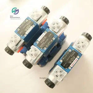
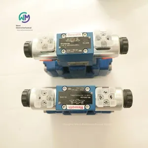
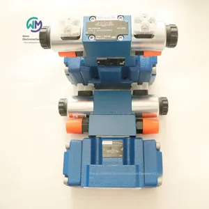
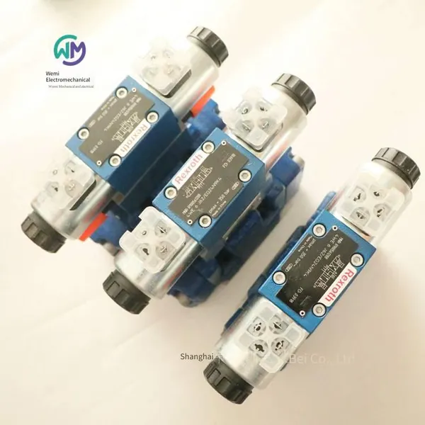
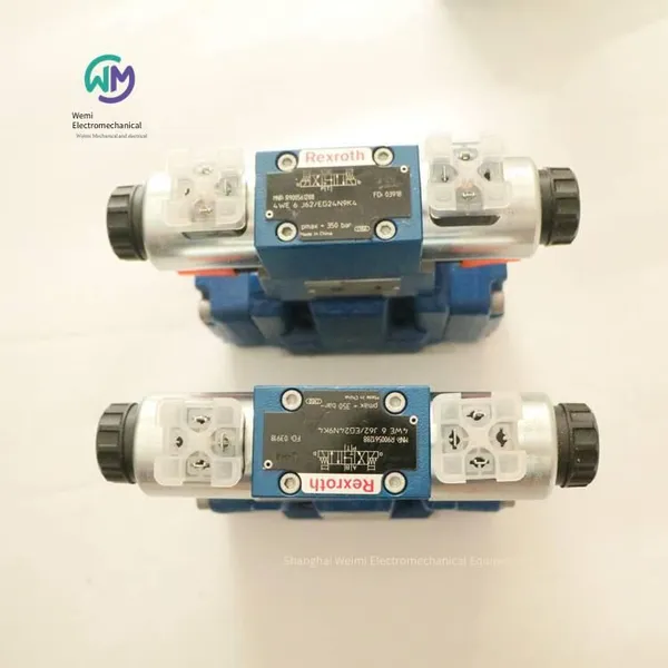
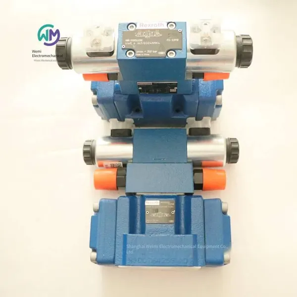
Rexroth Electro-hydraulic Directional Control Valve 4weh10j47/6eg24n9ets2k4



Related Products
-
 Rexroth Check Valve Z2s6-1-6x/can be Shipped on the Same DayUS$ 76.92 - 92.31MOQ: 1 Piece
 -
Aventics Oil Injection Valve 0821300936US$ 76.92 - 80MOQ: 1 Piece
-
Rexroth Check Valve Z1s6d05-40/vUS$ 146.15 - 153.85MOQ: 1 Piece
-
Italian Duplomatic Throttle Valve Mers-d/50US$ 110.77 - 115.38MOQ: 1 Piece
-
Rexroth Check Valve Z1s6t05-40/vUS$ 150.77 - 153.85MOQ: 1 Piece
REXROTH Electro-hydraulic directional control valve 4WEH10J47/6EG24N9ETS2K4, the main product of Shanghai Weimi Mechanical & Electrical Equipment Co., Ltd. Sales hotline: 13524123009; Contact person: Lei Qing; Product real-shot pictures. It's a 10-year-old store, offering original genuine products from the factory, with in-stock inventory and affordable prices. We sincerely welcome new and old customers to consult and purchase!
Rexroth REXROTH Pilot-operated directional spool valves with hydraulic or electro-hydraulic actuation
WEH, WH...6H
Size 16 … 25
Component series 1X
Maximum working pressure 350 bar
Maximum flow rate 650 l/min
Three-position four-way or two-position four-way directional control valve
Operation type (internal or external pilot control):
– Electro-hydraulic (Model WEH)
– Hydraulic (Model WH)
For subplate mounting
Port mounting surface complies with ISO 4401
Spring centered, spring end position
DC coil
Electrical connection as a single connection
Auxiliary operating device
Model WEH
WEH is a directional spool valve with electro-hydraulic drive. This valve controls the start, stop and direction of the flow.
The basic structure of this directional valve consists of a main valve with a housing, a main control spool, one or two return springs, and a pilot control valve with one or two magnets "a" and/or "b".
The main control spool in the main valve is held in the zero position or initial position by a spring or pressure build-up. In the initial position, the two spring chambers are connected to the oil tank in a pressure-relieved state through the pilot control valve. The pilot control valve is pilot-fed through the control oil circuit. The oil supply can be carried out internally or externally (external oil supply is achieved through port X). When the pilot control valve is operated (e.g. by magnet "a"), the pilot control spool moves to the left, thereby pilot-pressurizing the spring chamber. The spring chamber remains in a pressure-relieved state.
The pilot pressure acts on the left side of the main control spool and moves it against the spring force. This will connect port P with B and port A with T in the main valve.
When the electromagnet is turned off, the pilot control spool returns to the initial position. The spring chamber is unloaded to the oil tank.
The return oil of the pilot oil can be realized internally (through channel T) or externally (through channel Y).
Optional manual emergency operation can move the pilot control spool when the coil is de-energized.
Note:
The return spring in the spring chamber can keep the main control spool in the center position even when the valve is in the vertical position and there is no pilot pressure.
Due to the design principle, internal leakage of the valve is inevitable, and the leakage volume will increase with the increase of service time.
Model WH
Valve type WH is a directional spool valve with hydraulic operation. This valve controls the start, stop, and direction of the flow. The basic components of this directional valve are the valve body, the main control spool, one or two return springs for spring return and spring centering in the valve, and the flow distribution valve plate.
The main control spool is directly driven by pressure build - up. The main control spool is kept in the zero position or the initial position by the spring or pressure build - up. Both the supply and return of the pilot oil are realized externally.
Three - position four - way directional valve with spring centering of the control spool
In this model, the main control spool is kept in the zero position by the return spring. The spring chamber is connected to port Y and the spring chamber is connected to port X through the flow distribution valve plate.
Among the two front - side pilot pressures of the main control spool, when one of the pilot pressures is applied, the spool will move to the switching position. In the valve, the required ports will be connected in this way. When the pressurized control spool area is depressurized, the spring on the opposite side will push the spool back to the zero position or the initial position.
Model WH…
The pilot oil is supplied and returned externally through channels X and Y.
Model WEH...
The pilot oil is supplied externally from a separate pressure supply oil circuit through channel X.
The pilot oil flows into the oil tank through channel Y for external return.
Model WEH…E…
The pilot oil is supplied internally through channel P of the main valve.
The pilot oil flows into the oil tank through channel Y for external return. In the base plate, port X is closed.
Model WEH...ET...
The pilot oil is supplied internally through channel P of the main valve.
The pilot oil flows into the oil tank through channel T for internal return. In the base plate, ports X and Y are closed.
Model WEH...T...
The pilot oil is supplied externally from a separate pressure supply oil circuit through channel X.
The pilot oil flows into the oil tank through channel T for internal return. In the base plate, port Y is closed.
Note:
Modification of the pilot oil supply can only be carried out by authorized professionals or returned to the factory for execution.
Pilot oil external supply X or return Y:
The maximum allowable operating parameters of the pilot control valve must be complied with.
Maximum pilot pressure: Please comply with the requirements of the technical data!
Pilot oil supply internally (models “ET” and “E”):
Small pilot pressure: Please comply with the requirements of the technical data.
To avoid abnormal high-pressure peaks, a “B10” throttle insert must be provided at the port P of the pilot control valve.
Throttle insert
If you want to limit the pilot oil supply in the passage P of the pilot control valve, a throttle insert is required. The throttle insert will be inserted into the passage P of the pilot control valve.
Order numbers and models of German Rexroth electro-hydraulic directional valves:
R900778744 4WEH10D47/6EG24N9K4/B10D3
R900556904 4WEH10J47/6EG24N9ETS2K4
R900926574 4WEH10J47/6EG24N9ETK4
R900951655 4WEH10J47/6EG24N9TS2K4
R900774752 4WEH16D72/6EG24N9ETS2K4/B10
R900705858 4WEH16E72/6EG24N9ETK4/B12
R900970663 4WEH16J72/6EG205N9EK4/B10
R901072797 4WEH16R72/6EW230N9ETS2K4
R900943534 4WEH22E7X/6EG24N9ETK4/B10
R901108960 4WEH22J76/6HG24N9ETK4/B10
R900940965 4WEH16J72/6EG24N9ETS2K4/B10D3
Rexroth relief valves of series 0532 and R917
Features
Connection types for pipe installation and manifold installation
Adjustment methods, such as handwheel, non-adjustable, sealed, with graduated knobs (with and without lock).
Applications
Conveying and handling equipment, agricultural machinery field, urban vehicles and general mechanical engineering field.
Notes
Models that comply with the Pressure Equipment Directive 97/23/EG and “the safety valve model is certified by TÜV German Technical Inspection Agency” can be used to protect hydraulic accumulators.
Functions
This model series is based on a seat design with a damping piston. A punched seat is used to ensure high sealing performance, and the damping piston prevents any vibration of the valve. It can produce smooth control characteristics, that is, even when the flow rate increases, the set opening pressure can be largely maintained. This can be achieved by the effect of the hydrodynamic force on the valve disc, and the valve will continue to open as the flow rate increases.
Available general model types:
– Pipe-mounted housings with and without test ports.
– Spool valves for manifold block installation.
– Multiple adjustment methods, such as handwheels, non-adjustable, lead-sealed, with graduated knobs (with and without locks).
– A check valve is installed in front of the damping piston for faster response time.
Technical data
Design: Seat valve with damping
Line connection: For pipe installation and manifold block installation
Ambient temperature: –30...+80°C
Pressure medium: Hydraulic oil with a basic component of mineral oil in accordance with DIN/ISO
Viscosity: Permissible range: 10...800 mm2/s; Recommended range: 20...100 mm2/s; Permissible range at startup: ...2000 mm2/s
Pressure medium temperature: –30°C...+80°C with NBR seals; –15°C...+120°C with FKM seals.
Filtration: Oil contamination class 19/16 in accordance with ISO/DIS 4406.
Working pressure: For pipe installation, P: Maximum allowable pressure 350 bar, depending on load changes and temperature; T: Maximum allowable pressure 210 bar (NBR) or 80 bar (FKM), depending on load changes and temperature. For manifold block installation, P: In accordance with the set pressure. T: Maximum 210 bar for NBR, maximum 80 bar for FKM
Cracking pressure (tolerance pnominal +5%) set at a flow rate of 0.1 l/min
Flow rate: Maximum 120 l/min
Ordering models of German Rexroth REXROTH relief valves:
0532002048
0532004208
0532001051
0532004007
0532002062
0532003003
0532002002
0532001174
Rexroth pressure limiting valves, direct control DBD series
Size: 6 … 30
Component series: 1X
Maximum working pressure: 630 bar
Maximum flow rate: 350 l/min
Used as a screw-in cartridge valve (cartridge)
For threaded connections
For base plate installation
Adjustment types for pressure adjustment, optional:
-Hexagon socket and protective cap
-Knob
-Handwheel
- Lockable knob
Anti-corrosion design
The DBD type relief valve is a direct-acting seat valve. These valves are used to limit the system pressure.
These valves are mainly composed of the following components: sleeve, spring, valve core with damping plunger (pressure rating 25 bar … 400 bar) or ball (pressure rating 630 bar), and adjustment type. The adjustment type can be used to steplessly adjust the system pressure. The spring pushes the valve core or ball onto the valve seat. Port P is connected to the system. The pressure existing in the system will act on the surface of the valve core (or ball). If the pressure in port P exceeds the value set on the spring, the valve core or ball will open against the spring. At this time, the hydraulic oil flows from port P to port T. The stroke of the valve core is limited by the knurling.
In order to achieve good pressure regulation over the entire pressure range, the entire pressure range has been divided into 7 pressure ratings. One pressure rating corresponds to the maximum working pressure that can be set by a specific spring.
Note:
The adjustment type is specially constructed to prevent it from being lost. Thanks to the gimbal design, the adjustment element in the adjustment type will remain loose (movable) after being fully unloaded.
Pressure rating "25": Although the adjustment type is in the fully unloaded state, if the minimum pressure is not determined, the adjustment element will still "return" to the stop state under the action of a small spring force and/or restoring force.
After pressure adjustment/boosting, the adjustment element can be screwed in again.
Ordering models of German Rexroth REXROTH relief valves:
R900424196 DBDH6G1X/200
R900427242 DBDH6P1X/200
R900424201 DBDH6K18/315
R900423718 DBDS6G1X/25
R900423722 DBDS6G1X/50
R900433216 DBDS6G1X/315V
R900769384 DBDS6K1C/200E
R900423730 DBDS6P1X/315
R900423731 DBDS6P1A/400
R900423726 DBDS6K1X/400
R900433216 DBDS6G1A/315V
R900424745 DBDS10G1X/50
R900424158 DBDS10P1A/315
R900424157 DBDS10P1X/200
R900424158 DBDS10P1X/315
R900425660 DBDS10P1X/400
R900424271 DBDS20K1X/315
R900746472 DBDS30G1A/200-170
R900424348 DBDH6G1X/400
R900423743 DBDS10G1X/25
R900424149 DBDS10K18/200
R900424271 DBDS20K18/315
Rexroth direct-acting 2/4-way and 3/4-way proportional directional valves without electrical position feedback and without integrated electronics (OBE)
4WRA
Size 6, 10
Component series 2X
Maximum working pressure 315 bar
Maximum flow rate 75 l/min
Direct-acting proportional directional valves without electrical position feedback and with external electronics
Control the flow direction and flow rate of hydraulic oil
Operated by proportional solenoids with centering threads and removable coils
For subplate mounting: Hole pattern according to ISO 4401
Spring-centered control spool
In the valve plate design, 2/4-way and 3/4-way proportional directional valves are used as direct-acting devices. They are operated by proportional solenoids with centering threads and removable coils. The coils are controlled by external control electronics.
Configuration:
The basic components of the valve include:
Housing with connection surface
Control spool with compression spring
Coil with centering thread
After the coil is de-energized, the control spool is held in the center position by the compression spring
The control spool is directly operated by energizing the proportional solenoid, for example, energizing coil "b"
Move the control spool to the left in proportion to the electrical input signal
Connect from P to A and from B to T through the throttling cross-section with progressive fluid characteristics
De-energize the coil
The control spool returns to the center position under the action of the compression spring
Valves with two spool positions (Model 4WRA...A...):
Basically, the function of this type of valve corresponds to that of valves with three spool positions. However, this two-spool position valve is only equipped with coil "a". It is equipped with a protective plug for NG 6 or a cover for NG10 instead of the second proportional solenoid.
Note:
The tank line must not be run empty. Under the corresponding installation conditions, a preload valve (preload pressure about 2 bar) must be installed.
Ordering models of German REXROTH proportional directional valves:
R900902095 4WRA6W30-23/G24N9K4/V
R900902095 4WRA6W30-22/G24N9K4/V
R900902097 4WRA10E60-2X/G24N9K4/V
R900907650 4WRA10W60-2X/G24N9K4/V
R901054483 4WRA10EA00-22/G24K4/V-828
R900579943 4WRSE10V50-3X/G24K0/A1V
R900579286 4WRSE10V80-3X/G24K0/A1V
REXROTH direct-acting 2/4-way and 3/4-way proportional directional valves 4WRAE without electrical position feedback and with integrated electronics (OBE)
Size 6, 10
Component series 2X
Maximum working pressure 315 bar
Maximum flow rate 75 l/min
Direct-acting proportional directional valves without electrical position feedback and with integrated electronics (OBE)
Control the flow direction and flow rate of hydraulic oil
Operated by proportional solenoids with centering threads and removable coils
For subplate mounting: Hole pattern according to ISO 4401
Spring-centered control spool
In the valve plate design, 2/4-way and 3/4-way proportional directional valves are used as direct-acting devices. They are operated by proportional solenoids with centering threads and removable coils. The coils are controlled by integrated electronics.
Configuration:
The basic components of the valve include:
Housing with connection surface (1)
Control spool (2) with compression springs (3 and 4)
Coils with centering threads (5 and 6)
Integrated electronics (7)
After the coils (5 and 6) are de-energized, the control spool (2) will be held in the center position by the compression springs (3 and 4)
By energizing the proportional solenoid, for example, energizing the coil "b" (6), the control spool (2) is directly operated
The control spool (2) moves to the left in proportion to the electrical input signal
Connections from P to A and from B to T are made through throttle cross-sections with progressive fluid characteristics
Turn off the coil (6)
The control spool (2) returns to the center position under the action of the compression spring (3)
Valves with two spool positions (Model 4WRA...A...):
Basically, the function of this valve model corresponds to that of a valve with three spool positions. However, this double-spool position valve is only equipped with coil "a". It is equipped with a protective plug (8.1) with NG 6 or a cover (8.2) with NG10 to replace the second proportional solenoid.
Note:
The tank line must not be run empty. Under the corresponding installation conditions, a preload valve (preload pressure approximately 2 bar) must be installed.
Examples of model details:
4WRAE6E30-23/G24K31/A1V
4 → 4 main oil ports
WRAE → Proportional directional valve with integrated electronics
6 → Nominal size 6 (Nominal size 6, Nominal size 10)
E → Oil circuit function type (E, E1, W, W1, EA, WA)
30 → Rated flow rate: 30 l/min for nominal size 6 (7 l/min, 15 l/min)
Rated flow rate for nominal size 10 (30 l/min, 60 l/min)
23 → Component series 20 ... 29 (20 ... 29: Installation and connection dimensions remain unchanged)
G24 → Power supply voltage 24 V
K31 → Connector DIN EN 175201-804
A1 → Control value ±10 V (F1 = Control value 4 to 20 mA)
V → Sealing material FKM seals (M = NBR seals)
Hydraulics
Model 4WRAE
Specification 6 10
Installation position Any position, preferably horizontal
Ambient temperature range -20 … +50°C
Storage temperature range -20 … +80°C
Weight: 2.2kg 6.8kg
Hydraulic oil Mineral oil (HL, HLP) complying with DIN 51524
Hydraulic oil temperature range -20 … +80°C (+40 … +50℃)
Viscosity range 20 … 380mm²/s (30 … 46mm²/s)
Maximum allowable contamination level of hydraulic oil, cleanliness level complying with ISO 4406 (c) Grade 20/18/15 complying with ISO 4406 (c)
Hysteresis ≤ 5%
Reverse dead zone ≤ 1%
Response sensitivity ≤ 0.5%
Electrical
Voltage type: DC voltage
Maximum coil current: 2.5A
Maximum current consumption
Amplifier: 1.8A
Amplifier (pulse current): 3A
Electromagnetic coil resistance
Low-temperature value at 20 °C: 2Ω
Maximum high-temperature value: 3Ω
Startup time: 100%
Maximum coil temperature: + 150°C
Power supply: 24VDC
Power supply voltage range: 19 … 35V
Control value input "A1": ± 10V
Control value input range "F1": 4 … 20mA
Material numbers and models of German Rexroth proportional valves:
R900954071 4WRAE6E30-23/G24K31/A1V
R900965674 4WRAE10E60-2X/G24K31/F1V
R900954083 4WRAE10E60-2X/G24K31/A1V
R900558356 4WRAE10E60-2X/G24N9K31/A1V
R900929318 4WRAE10E60-2X/G24N9K31/F1V
R900710530 4WRAE10W60-2X/G24K31/F1V
R900954088 4WRAE10W60-22/G24K31/A1V
R900900988 4WRAE10W60-2X/G24N9K31/A1V
R900920055 4WRAE10W60-2X/G24N9K31/F1V
R900954089 4WRAE10W1-60-2X/G24K31/A1V
R900732536 4WRAE10W1-60-2X/G24K31/F1V
R900936006 4WRAE10W1-60-2X/G24N9K31/A1V
R900949757 4WRAE10W1-60-2X/G24N9K31/F1V
Rexroth direct-acting 2/4-way and 3/4-way proportional directional valves 4WRE with electrical position feedback and without integrated electronics (OBE)
Specification 6
Component series 2X
Maximum working pressure 315 bar
Maximum flow rate 80 l/min
Direct-acting proportional directional valve with electrical position feedback and external electronic components
Adjust the direction and magnitude of the volumetric flow rate
Operated by proportional solenoids with centering threads and detachable coils
For subplate mounting: Hole pattern according to ISO 4401
Spring-centered control spool
Model 4WRE...-2X/...
In the valve plate design, two-position four-way and three-position four-way proportional directional valves are used as direct-acting devices. They are operated by proportional solenoids with centering threads and detachable coils. The coils are controlled by external electronic components.
Configuration:
The basic components of the valve include:
Housing with connection surface (1)
Control spool (2) with compression springs (3 and 4) and spring seats (5 and 6)
Coils with centering threads (7 and 8)
Position sensor (9)
After the coils (7 and 8) are de-energized, the compression springs (3 and 4) between the spring seats (5 and 6) can place the control spool (2) in the center position
The control spool (2) can be directly operated by controlling the proportional solenoid (e.g., coil "b" (8))
The control spool (2) moves to the left in proportion to the electrical input signal
Through the throttling cross-section with progressive flow characteristics,
Connections from P to A and from B to T are made
Turn off the coil (8)
The control spool (2) returns to the center position under the action of the compression spring (3)
Function:
In the de-energized state, the return spring of the coil keeps the control spool (2) in the mechanical center position. When using a control spool with the symbol "V", this position does not correspond to the hydraulic center position! When the electric valve control loop is closed, the control spool will be in the hydraulic center position.
Important notes:
The PG assembly (11) must not be opened. The mechanical adjustment of the adjusting nut at the bottom is disabled. This operation will damage the valve!
Valve with two spool positions: (Model 4WRE…A...)
Basically, the function of this type of valve corresponds to that of a valve with three spool positions. However, this two-spool position valve is only equipped with coil "a" (7). It is equipped with a protective plug (10) instead of the second proportional solenoid.
Note:
Due to the design principle, there is inherent internal leakage in the valve, and the leakage amount may increase with the service life.
Note:
The tank line must not be operated empty. Under the corresponding installation conditions, a preload valve (preload pressure about 2 bar) must be installed.
Model example:
4WRE6V16-22/G24K4/V
4 → 4 main oil ports
WRE → Proportional directional valve with electrical position feedback
6 → Nominal size 6 (Nominal size 10)
V → Function symbol (E; E1-; V; V1-; W; W1-; EA; WA)
16 → Rated flow NG6 16 l/min (4 l/min, 8 l/min, 32 l/min)
Rated flow NG10 (25 l/min, 50 l/min, 75 l/min)
22 → Component series 20 ... 29 (20 ... 29: Installation and connection dimensions remain unchanged)
G24 → Power supply voltage 24 V
K4 → Connector DIN EN 175301-803
V → FKM seals (M = NBR seals)
Model 4WRE
Specification 6
Installation position Any position, preferably horizontal
Ambient temperature range -20 … +70°C
Storage temperature range -20 … +80°C
Weight 2.2kg
MTTFD value complies with EN ISO 13849 150y
Maximum working pressure 315bar
Maximum working pressure
Port P 315bar
Port T 210 bar
Anschluss A 315 bar
Port B 315bar
Maximum flow 80l/min
Rated flow 4l/min 8l/min 16l/min 32l/min
Hydraulic oil HL, HLP
Hydraulic oil temperature range -20 … +80°C (+40 … +50℃)
Viscosity range 20 … 380mm²/s (30 … 46mm²/s)
Maximum allowable contamination level of hydraulic oil, conforming to the cleanliness level specified in ISO 4406 (c)
Grade 20/18/15 conforms to ISO 4406 (c)
Hysteresis ≤ 0.1%
Reverse dead zone ≤ 0.05%
Response sensitivity ≤ 0.05%
Zero drift when changing the following items
Hydraulic oil temperature ≤ 0.15%/10 K
Working pressure ≤ 0.1%/100 bar
Electrical
Specification 6
Voltage type DC voltage
Maximum current consumption
(Amplifier) 2A
(Amplifier (pulsed current)) 3A
Electromagnetic coil resistance
Low temperature value at 20 °C 2.65Ω
Maximum high temperature value 4.05Ω
Startup time 100%
Maximum coil temperature 150°C
Protection class according to DIN EN 60529 IP65 (if a suitable and correctly installed connection plug is used.)
Power supply 24V
Power supply voltage range 19.4 … 35V
Material numbers and models of German Rexroth proportional valves:
R901036556 4WRE6V16-22/G24K4/V-822
Rexroth pilot-operated high-frequency directional valve with integrated electronics (OBE) and electrical position feedback
4WRDE
Specification 10 … 27
Component series 6X
Maximum working pressure 350 bar
Maximum flow rate 1000 l/min
Nominal flow rate 25 … 500 l/min
- High response sensitivity and low hysteresis
High quality - Servo valve performance pilot control valve controls the spool and sleeve
Flexible - Suitable for position, rate, force and pressure control in highly dynamic applications
Reliable - Proven and robust design
The 4WRDE type valve is a three-stage pilot-operated directional control valve with electrical position feedback and integrated electronics (OBE).
Settings
The basic composition of the valve is:
4WS2EM6-2X model two-stage booster mode pilot control valve
Main stage including the housing and main stage control spool
Integrated electronics with main stage inductive position sensor
Function
In the integrated electronics (OBE), the control value of the main stage control spool will be compared with the theoretical position value. In the case of a difference (control deviation), the first stage of the pilot control valve will be controlled (dry torque motor and nozzle flapper system). In this way, the deflection of the flapper of the nozzle flapper system can be achieved. The distance between the flapper and one of the two control nozzles through which the pilot oil flows will decrease, while the distance to the other nozzle will increase. Through the connection holes, similar to the control signal, the resulting flow difference causes the control spool to deflect in the pilot control valve (second stage). The flow released by the pilot control valve causes the main stage (third stage) control spool to deflect until its actual position value matches the control value. The stroke of the control spool is controlled by the proportion of the control value.
Valve Features
The factory setting of the valve is the oscillation default setting, and the constant frequency is 400 Hz.
Power supply voltage fault
After applying the pilot oil pressure, the main control spool will move to an undefined terminal position. The acceleration force generated in this connection may cause mechanical damage.
If a directional stacking valve is used (please refer to the order code), the two pilot oil chambers of the main stage will be short-circuited in the event of a power failure.
For symbols E, E1-, W6, and W8, the main spool will be centered by springs at the center position.
For symbols V and V1, the main spool will use a spring-operated offset position (P - B and A - T) (tolerance range is 1% ... 11% of the control spool stroke)
Note:
Changing the zero potential and/or the amplitude of the flutter current may cause system damage, so it can only be performed by professional personnel.
The pilot control valve can only be maintained by Rexroth employees. There is an exception, which is to replace the filter and seals according to the accessory list. During assembly, it must be ensured that the seals are correctly fixed and the protective plug is tightened. The tightening torque of the protective plug is 30 Nm.
Model "Y"
External pilot oil supply, external pilot oil return
In this model, the pilot oil is supplied by a separate pilot oil circuit (externally). The pilot oil return does not flow into the T channel of the main valve, but flows into the oil tank separately through port Y (externally).
Model "PY"
Internal pilot oil supply, external pilot oil return
When using this model, the pilot oil is supplied by the P channel of the main valve (internally). The pilot oil return does not flow into the T channel of the main valve, but flows into the oil tank separately through port Y (externally). In the base plate, port X must be closed.
Model "PT"
Internal pilot oil supply, internal pilot oil return
When using this model, the pilot oil is supplied by the P channel of the main valve (internally). The pilot oil flows directly back to the T channel of the main valve (internally). In the base plate, ports X and Y must be closed.
Model "XT"
External pilot oil supply, internal pilot oil return
In this model, the pilot oil is supplied by a separate pilot oil circuit (externally). The pilot oil flows directly back to the T channel of the main valve (internally). In the inlet manifold, port Y must be closed.
Material numbers and models of German Rexroth REXROTH electro-hydraulic proportional valves:
R901469206 4WRDE10V1-100L-60/MXY/24A5
R901144795 4WRDE27W500L-53/6L24K9/MR
R901538130 4WRDE27W6-500L-60/MXY/24A5
REXROTH Electro-hydraulic directional control valve 4WEH10J47/6EG24N9ETS2K4

Send Inquiry to This Supplier


You May Also Like
-
Rexroth Pressure Limiting Valve Dbds30g1a/200-170US$ 243.08 - 246.15MOQ: 1 Unit
-
Duplomatic Stacked Throttle Valve Mers-rd/50US$ 123.08 - 126.15MOQ: 1 Piece
-
Aventics Pneumatic Valve 5672310000US$ 376.92 - 384.62MOQ: 1 Piece
-
Aventics Solenoid Valve Body 0820022991US$ 141.54 - 146.15MOQ: 1 Piece
-
Rexroth Piston Pump Aa10vso28dfr/31r-ppa12n00US$ 1092.31 - 1307.69MOQ: 1 Piece
-
Rexroth Pressure Relief Valve Dbdh6g1x/400US$ 138.46 - 146.15MOQ: 1 Piece
-
Rexroth Proportional Valve Amplifier Board 0811405104US$ 638.46 - 653.85MOQ: 1 Piece
-
Aventics Pull Rod Cylinder 0822343004US$ 187.69 - 190.77MOQ: 1 Piece
-
Aventics Filter Pressure Regulator R412009210US$ 212.31 - 215.38MOQ: 1 Piece
-
German Aventics Valve Island R480034030US$ 938.46 - 953.85MOQ: 1 Piece


