








 Contact Platform Support
 Help Center
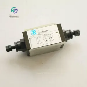
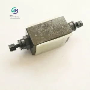
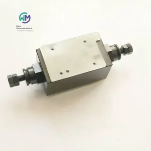
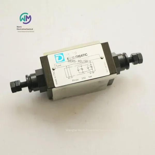
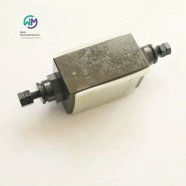
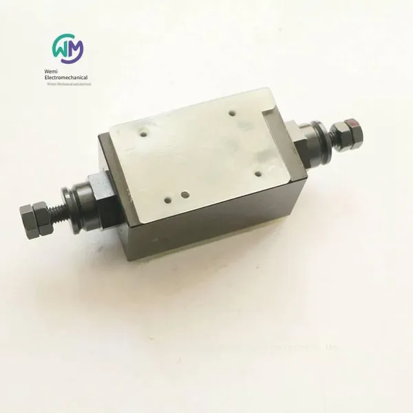
Duplomatic Stacked Throttle Valve Mers-rd/50



Related Products
-
 Aventics Pneumatic Valve 5672310000US$ 376.92 - 384.62MOQ: 1 Piece
 -
Aventics Solenoid Valve Body 0820022991US$ 141.54 - 146.15MOQ: 1 Piece
-
Rexroth Piston Pump Aa10vso28dfr/31r-ppa12n00US$ 1092.31 - 1307.69MOQ: 1 Piece
-
Rexroth Pressure Relief Valve Dbdh6g1x/400US$ 138.46 - 146.15MOQ: 1 Piece
-
Rexroth Proportional Valve Amplifier Board 0811405104US$ 638.46 - 653.85MOQ: 1 Piece
DUPLOMATIC Stacked Throttle Valve MERS-RD/50, the main product of Shanghai Weimi Mechanical & Electrical Equipment Co., Ltd. Sales hotline: 13524123009; Contact person: Lei Qing; Product real-shot pictures, original genuine products, in-stock inventory, affordable price; Warmly welcome new and old customers to consult and purchase!
Italian DUPLOMATIC Throttle Valve MERS
Stacked type
ISO 4401-03
High working pressure 350 bar
This valve is a stacked flow control valve without pressure compensation. The integrated check valve allows the oil to flow freely in the reverse direction. Its mounting surface size complies with the ISO 4401 standard. This valve can be combined with other valves complying with the CETOP 03 standard into a stacked valve group through bolts or screws without oil pipe connection.
This valve can also provide a reversible form (G* type). The selection of inlet throttling and outlet throttling depends on its installation direction on the mounting plate with an O-ring.
All models of valves are integrated with a check valve, allowing the oil to flow freely in the reverse direction (opening pressure 0.5 bar).
It is usually supplied with a hexagonal adjusting screw.
Structure
“SA”: Control the flow from the actuator into line A.
“SB”: Control the flow from the actuator into line B.
“D”: Control the discharge flow from the two chambers of the actuator respectively. (Standard)
“RD”: Control the input flow into the two chambers of the actuator respectively.
“G*”: Reversible valve.
Technical parameters (measured at an oil temperature of 50°C and an oil viscosity of 36 cSt)
Maximum working pressure 350 bar
Check valve opening pressure 0.5 bar
Maximum flow rate of the control line 50 l/min
Maximum flow rate of the free line 75 l/min
Minimum control flow rate at ∆p 10 bar ≤0.060 l/min
Ambient temperature range -20 / +50°C
Oil temperature range -20 / +80°C
Oil viscosity range 10 ÷ 400 cSt
Permissible pollution level of the oil According to ISO 4406:1999 level 20/18/15
Recommended oil viscosity 25 cSt
Weight 1.3 kg
Hydraulic oil
When using mineral hydraulic oil HL or HM complying with the ISO 6743-4 standard, use NBR seals. For HFDR oil (phosphate ester), use FPM seals (code V).
Ordering models of Italian DUPLOMATIC throttle valves:
MERS-RD/50
MERS-D/50
MERS-SA/50
MERS-SB/50
Italian DUPLOMATIC DSC3 Hydraulic Control Directional Control Valve
Plate installation
ISO 4401-03
The DSC3 valve is a hydraulic control directional control valve, offering three-way or four-way designs, and has various interchangeable spools. The mounting surface dimensions comply with the ISO 4401 (CETOP RP121H) standard.
The valve body is made of high-strength cast iron, with wide flow channels cast inside the valve body to reduce pressure loss.
This valve can be provided with a 2-position or 3-position design with spring return, or a 2-position design with mechanical return.
Maximum working pressure:
Oil ports - P A B - 350 bar
Oil port - T - 25 bar
Pilot pressure:
- min 15 bar
- max 210 bar
Nominal flow rate 75 l/min
Ambient temperature range -20 / +50 °C
Oil temperature range -20 / +80 °C
Oil viscosity range 10 ÷ 400 cSt
Maximum allowable pollution level of the oil According to ISO 4406:1999, grade 20/18/15
Recommended oil viscosity 25 cSt
Mass:
Single control valve 1.3 kg
Dual control valve 1.7 kg
Hydraulic oil
When using mineral hydraulic oil HL or HM that complies with the ISO 6743-4 standard, use NBR seals (code N). For HFDR oil (phosphate ester), use FPM seals (code V).
Installation
Valves with spring centering and return can be installed in any direction; RK-type valves without springs and with mechanical positioning must be installed horizontally along the longitudinal axis. The valve can be installed on a flat surface by screws or bolts. The flatness and roughness levels of the mounting surface must be equal to or higher than the values shown in the figure. If the flatness or roughness does not meet the required minimum values, oil leakage is likely to occur between the valve and the mounting surface.
Ordering models of Italian DUPLOMATIC Hydraulic Control Directional Valves:
DSC3-SA1/11V
Italian DUPLOMATIC Manual Directional Control Valve DSH
Panel mounting
DSH3 ISO 4401-03
DSH5 ISO 4401-05
DSH* is a manual directional control valve, offering three-way or four-way designs, and has
various interchangeable spools. — The valve body is made of high-strength cast iron, with wide flow channels cast inside the valve body to reduce pressure loss.
2-position and 3-position designs are available, with spring centering or mechanical return.
Relative to the standard position, according to the installation requirements, the handle of the DSH3 valve can be rotated 180°.
Technical parameters (measured at a temperature of 50°C and an oil viscosity of 36 cSt)
Maximum working pressure:
- Ports P - A - B
DSH3 350bar
DSH5 320bar
- Port T
DSH3 210bar
DSH5 160bar
Nominal flow rate
DSH3 75l/min
DSH5 150l/min
Ambient temperature range
DSH3 DSH5 -20 / +50℃
Oil temperature range
DSH3 DSH5 -20 / +80℃
Oil viscosity range
DSH3 DSH5 10 - 400cSt
Permissible contamination level of the oil According to ISO 4406:1999, grade 20/18/15
Recommended oil viscosity 25cSt
Weight
DSH3 2.1kg
DSH5 4.2kg
Hydraulic oil
When using mineral hydraulic oil HL or HM that meets the ISO 6743-4 standard, use NBR seals (code N). For HFDR oil (phosphate ester), use FPM seals (code V).
When the working oil temperature is higher than 80 °C, it will cause the hydraulic oil and seals to age and deteriorate rapidly. Please pay attention to maintaining the stable physical and chemical properties of the hydraulic oil.
Installation
Valves with spring centering and return can be installed in any direction; mechanically positioned valves must be installed horizontally along the longitudinal axis.
The valve can be installed on a flat surface by screws or bolts. The flatness and roughness levels of the installation surface must be equal to or higher than the values shown in the figure. If the flatness or roughness does not meet the required minimum values, oil leakage is likely to occur between the valve and the installation surface.
Italian DUPLOMATIC Manual Directional Control Valve
DSH3-S1/11N
DSH3-S2/11N
DSH3-S3/11N
DSH3-S4/11N
DSH3-SK1/11N
DSH3-SK3/11N
DSH3-SK4/11N
DSH3-TAK/11N
Italian DUPLOMATIC Direct-acting Three-way Pressure-reducing Valve MZD
Fixed or Variable Adjustment
Stackable
ISO 4401-03
Maximum Working Pressure 350 bar
The MZD stackable valve is a direct-acting three-way pressure-reducing valve. Normally, when the valve is not working, it is in the open state, and the oil can flow freely from pipeline P1 to pipeline P. One end of the valve spool bears the pressure of pipeline P, and the other end bears the force of the adjustment spring. When the pressure of pipeline P exceeds the set pressure of the spring, the valve closes until the pressure of pipeline P decreases to the set value.
The structure of the valve gives it good adjustment sensitivity, and the leakage of the valve is small. The oil drain port is connected to pipeline T inside the valve.
The three-way design allows the oil from the hydraulic actuator to flow back to port T for discharge, thus protecting the secondary circuit from pressure shocks.
This valve is for stackable installation. Its installation surface size conforms to the ISO 4401 standard and can be quickly installed under the solenoid valve conforming to the ISO 4401-03 standard without oil pipe connection.
It is usually supplied with an adjustable countersunk hexagon socket adjusting screw. The SICBLOC adjusting knob can also be selected according to requirements.
The pressure setting value of the fixed adjustment type valve can be 20, 25 or 30 bar.
Structure
MZD*: Pressure reduction of pipeline P, oil drain at port T.
MZD*/A and MZD*/RA: Pressure reduction of pipeline A connected to the actuator, pipeline B is at maximum pressure, oil drain at port T.
MZD*/B and MZD*/RB: Pressure reduction of pipeline B connected to the actuator, pipeline A is at maximum pressure, oil drain at port T.
Technical Parameters (Measured at an oil temperature of 50°C and an oil viscosity of 36 cSt)
Maximum Working Pressure 350 bar
Maximum Pressure at Port T 10 bar
Maximum Flow Rate of the Control Pipeline 50 l/min
Maximum Flow Rate of the Free Pipeline 75 l/min
Leakage Flow Rate ≤ 0.08 l/min
Ambient Temperature Range -20 / +50℃
Oil temperature range -20 / +80℃
Oil viscosity range 10 ÷ 400cSt
Permissible contamination level of the oil According to ISO 4406:1999, level 20/18/15
Recommended oil viscosity 25cSt
Mass 1.4kg
Hydraulic oil
When using mineral hydraulic oil HL or HM that complies with ISO 6743-4 standard, use NBR seals. For HFDR oil (phosphate ester), use FPM seals (code V).
When the working oil temperature is higher than 80 °C, it will cause the hydraulic oil and seals to age and deteriorate too quickly.
Please note to maintain the stable physical and chemical properties of the hydraulic oil.
Ordering models of Italian DUPLOMATIC three-way pressure reducing valves:
MZD3/RP/50
MZD2/50
MZD3/50
MZD5/50
MZD3/A/50
MZD3/B/50
MZD4/50
MZD4/A/50
MZD5/RP/50
Italian DUPLOMATIC pilot-operated pressure reducing valves, Z4M series
Stackable type
ISO 4401-05
Maximum working pressure 320 bar
The Z4M stackable valve is a pilot-operated pressure reducing valve, and its mounting surface size complies with
ISO 4401 (CETOP PR 121H) standard.
This valve can be used to reduce the pressure of the secondary circuit and can ensure the stability of the control pressure, even when the flow rate through the valve changes.
This valve can be quickly installed under the directional control valve that complies with ISO 4401-05 (CETOP 05) standard without tubing connection.
It is usually supplied with a countersunk hexagon socket adjusting screw, a lock nut and a maximum adjustment limiting device.
This valve can provide 4 different pressure adjustment ranges, with a maximum pressure of 320 bar.
Hydraulic function
Z4M*-I: Pressure reduction in the P line, oil drain at the T port.
Z4M*-A: Pressure reduction in the A line, full pressure in the B line.
Z4M*-B: Pressure reduction in the B line, full pressure in the A line.
Parameters
Maximum working pressure 320bar
Maximum flow rate of the control line P 80l/min
Maximum flow rate of the free line 100l/min
The flow rate of the oil drain pipeline ≤0.07l/min
Ambient temperature range: -20 / +50℃
Oil temperature range: -20 / +80℃
Oil viscosity range: 10 ÷ 400cSt
Permissible contamination level of oil: According to ISO 4406:1999, level 20/18/15
Recommended oil viscosity: 25cSt
Mass: 2.7kg
Hydraulic oil
When using mineral hydraulic oil HL or HM that complies with ISO 6743-4 standard, use NBR seals. For HFDR oil (phosphate ester), use FPM seals (code V).
Ordering model of Italian DUPLOMATIC pilot-operated pressure reducing valve:
Z4M5-I/50
Z4M3-I/50
Z4M4-I/50
Italian DUPLOMATIC throttle valve ERS4M
Stacked type
CETOP 05
p max 320 bar
Working principle
- This valve is a flow control valve without compensation. It has a built-in check valve that allows free reverse flow of the fluid. This valve is of the stacked type, and its installation dimensions comply with CETOP and ISO standards.
- Without the need for oil pipes, this valve can be quickly assembled with other CETOP 05 valves into a stacked valve group by bolts or screws.
- Usually, it is supplied with a SICBLOC knob. This knob has a scale indication and can be self-locking. Press and rotate it during operation.
Hydraulic functions:
- Function "SA": Used when it is necessary to control the flow rate from the actuator into pipeline A.
- Function "SB": Used when it is necessary to control the flow rate from the actuator into pipeline B.
- Function "D": Control the discharge oil volume from the two chambers of the actuator respectively.
- Function "RD": Control the input flow rate into the two chambers of the actuator respectively.
- All models of this valve have a built-in check valve that allows free reverse flow. (Opening pressure: 0.5 bar).
Technical parameters (measured at an oil temperature of 50℃ and an oil viscosity of 36cST)
Maximum working pressure: 320bar
Check valve opening pressure: 0.5bar
Maximum flow rate of the control pipeline: 80l/min
Maximum flow rate of the free pipeline: 100l/min
Ambient temperature range: –20 ~ +50℃
Oil temperature range: –20 ~ +70℃
Oil viscosity range: 2.8 ~ 380cSt
Recommended filtration accuracy: ≤ 25µm
Recommended oil viscosity: 25cSt
Weight: 3.1kg
Hydraulic oil
Normally, mineral oil with anti-foaming agent and antioxidant should be used.
Ordering model of Italian DUPLOMATIC throttle valve:
ERS4M-SB/40
Italian DUPLOMATIC throttle valve MERS
Stacked type
ISO 4401-03
Maximum working pressure: 350 bar
This valve is a stacked flow control valve without pressure compensation. The integrated check valve allows the oil to flow freely in the reverse direction. Its mounting surface size complies with the ISO 4401 standard. This valve can be combined with other valves complying with the CETOP 03 standard into a stacked valve group through bolts or screws without tubing connection.
This valve can also be provided in a reversible form (G* type). The selection of inlet throttling and outlet throttling depends on its installation direction on the mounting plate with O-ring.
Each model of the valve is integrated with a check valve, allowing the oil to flow freely in the reverse direction (opening pressure: 0.5 bar).
Normally, it is supplied with a hexagonal adjusting screw.
Structure
“SA”: Control the flow of oil flowing from the actuator into line A.
“SB”: Control the flow of oil flowing from the actuator into line B.
“D”: Control the discharge flow from the two chambers of the actuator respectively. (Standard)
“RD”: Control the input flow into the two chambers of the actuator respectively.
“G*”: Reversible valve.
Technical parameters (measured at an oil temperature of 50°C and an oil viscosity of 36 cSt)
Maximum working pressure: 350bar
Check valve opening pressure: 0.5bar
Maximum flow rate of the control line: 50l/min
Maximum flow rate of the free line: 75l/min
Minimum control flow rate at ∆p = 10 bar: ≤0.060l/min
Ambient temperature range: -20 / +50℃
Oil temperature range: -20 / +80°C
Oil viscosity range: 10 ÷ 400cSt
Permissible pollution level of the oil: According to ISO 4406:1999, grade 20/18/15
Recommended oil viscosity: 25cSt
Weight: 1.3kg
Hydraulic oil
When using mineral hydraulic oil HL or HM that complies with ISO 6743-4 standard, use NBR seals. For HFDR oil (phosphate ester), use FPM seals (code V).
Ordering models of Italian DUPLOMATIC throttle valves:
MERS-RD/50
MERS-D/50
MERS-SA/50
MERS-SB/50
Italian DUPLOMATIC logic elements
LC* cartridge valves
ISO 7368 - DIN 24342
LP* cover plates
LCM* logic elements with monitoring
ND 16 - 25 - 32 - 40 - 50 - 63
High working pressure 420 bar
Logic elements are a type of cartridge valve suitable for integral manifolds and are available in 6 different specifications.
Logic elements can realize complex hydraulic circuits by using functional and compact valve blocks, featuring large flow rates and low pressure drops.
Logic elements consist of cartridge valves with sockets complying with ISO7368 / DIN 24342 and control cover plates. The cover plates include the control oil passages of the cartridge valves; some models can be installed with valves complying with ISO4401-03 standard to achieve different control functions. Inserting a seal into valve seat 5 can obtain a low-leakage type.
— Cartridge valves are composed of valve sleeves, cone valve cores and return springs. The cone valve core can be of the standard type or the type with damping holes, and this structure is suitable for smooth flow control when the valve opens and closes.
— There are two different types of cartridge valves to choose from
- Type Q: This valve is used for flow and direction control or as a check valve.
A1 - The area of the valve seat, defined as the reference area = 1
A3 - The inner ring area of the valve sleeve
A2 - The area difference between A3 and A1
The area ratio A1/A3 is 1/1.66.
The valve opens when the pressure acting on area A1 or area A2 is higher than the pressure acting on area A3.
- Type P: This valve is used for pressure control.
The areas A1 and A3 of this valve are equal and only allow flow from A to B.
— LCM* are logic elements with monitoring, used for direction control, piloting and as check valves. These valves are TÜV certified. Specifications DN 16, 25, 32, 40 and 50 are available.
Hydraulic oil
When using mineral hydraulic oil HL or HM that complies with ISO 6743-4 standard, use NBR seals. For HFDR oil (phosphate ester), use FPM seals (code V).
Technical parameters (Cartridge valve with cover plate)
LC cartridge valve Maximum working pressure 420bar
Cover plates of types DP*, DPE*, DF1, DF2, LCM Maximum working pressure limit 350bar
Ambient temperature range -20 / +50℃
Oil temperature range -20 / +80℃
Oil viscosity range 10 ÷ 400cSt
Permissible contamination level of oil According to ISO 4406:1999, grade 20/18/15
Recommended oil viscosity 25cSt
Function description of cartridge valve cover plate:
1. Type R cover plate, directional control and check valve functions, external pilot X:
The pilot control of the cartridge valve is achieved through port X, which can be provided by the mounting surface or connected by a 1/4" BSP pipe.
For the specifications of ND 40 and ND 50, the external pilot function can be achieved by using the type D cover plate, which must be used with a blind plate. Code 1950751 (to be ordered separately).
2. Type D cover plate, directional control and check valve functions:
The pilot control of the cartridge valve is achieved through the solenoid valve DS3 - TA (to be ordered separately)
Solenoid valve de - energized = No flow between A ↔ B
Solenoid valve energized = Free flow between A ↔ B
3. Type DZ cover plate, directional control and can be used as the pilot control for other cartridge valves in the oil circuit:
The type DZ cover plate can provide pilot control for its own cartridge valve, and at the same time, it can also provide control for other cartridge valves connected to the pilot oil circuits Z1 and Z2.
The pilot solenoid valve DS3 - S10 must be ordered separately
4. Type DF1 cover plate, directional control and check valve functions, dual pilot:
The type DF1 cover plate provides dual pilot control through ports X and Z1.
The pilot solenoid valve DS3 - TA must be ordered separately.
Solenoid valve de - energized = No flow between A↔B
Solenoid valve energized = Free flow from A → B, no flow from B → A.
5. Type DF2 cover plate, directional control and check valve functions, two - way pilot priority control selection:
The cartridge valve can obtain pilot control oil from both the X and Z1 pipelines at the same time.
The shuttle valve integrated in the cover plate can automatically select the pipeline with higher pressure as the pilot control pipeline (priority pipeline).
The pilot solenoid valve DS3 - TA must be ordered separately.
Solenoid valve de - energized = No flow between A ↔ B
Solenoid valve energized = Free flow between A and B
6. Q-type cover plate, flow control function:
The flow control function is realized through the stroke limiter of the cover plate.
In order to obtain better flow control and prevent seat wear, it is usually used in conjunction with the cartridge valve of type QD4.
7. DP* type cover plate, pressure control function:
The cover plate integrates a relief valve to achieve the pressure control function.
Maximum adjustment pressure: DP4 = 140 bar - DP6 = 350 bar
The top blind plate 1950591 must be ordered separately.
The pressure control function with electrical unloading is realized through the solenoid valve DS3 - SA2.
(The solenoid valve needs to be ordered separately)
- Solenoid valve de-energized = Unloading under low pressure
- Solenoid valve energized = Pressure control is achieved through the integrated relief valve
The pressure control function with electrical unloading and two-stage pressure is realized through the solenoid valve DS3 - S2. The solenoid valve needs to be ordered separately.
MCI*-SAT/10 (Suitable for sizes 16, 25 and 32 - need to be ordered separately) and MCD*-SAT (Suitable for sizes 40, 50 and 63 - need to be ordered separately)
Solenoid valve de-energized = Unloading under low pressure
Solenoid valve a electromagnet energized = Pressure control is achieved through the relief valve integrated in the cover plate
Solenoid valve b electromagnet energized = Pressure control is achieved through the relief valve (MCI* or MCD*)
The pressure control function with electrical unloading and three-stage pressure is realized through the solenoid valve DS3 - S3. (The solenoid valve needs to be ordered separately),
MCI*-DT/10 (Suitable for sizes 16, 25 and 32 - need to be ordered separately) and MCD*-DT/51 (Suitable for sizes 40 and 50 - need to be ordered separately)
Solenoid valve de-energized = Pressure control is achieved through the relief valve integrated in the cover plate.
Solenoid valve a electromagnet energized = Pressure control is achieved through the relief valve at port b.
Solenoid valve b electromagnet energized = Pressure control is achieved through the relief valve at port a.
8. DPE* type cover plate, pressure control function:
The pressure control function is realized through the proportional relief valve PRED3
(The proportional valve needs to be ordered separately, see sample 81 210).
- Maximum adjustment pressure: DPE4 = 140 bar - DPE6 = 350 bar
- Proportional valve de-energized = Unloading at low pressure
- Proportional valve energized = Pressure control is achieved by the proportional valve
Logic elements with monitoring
The logic element with monitoring consists of an insert valve with directional function and a cover plate with a built-in inductive proximity sensor.
The closed contact of the PNP sensor indicates no flow between A and B.
The logic element with monitoring LCM* has been tested by TÜV on a voluntary basis and meets the application requirements of the following standards:
▪ UNI EN ISO 4413:2012 - Hydraulic fluid power – General rules and safety requirements for systems and their components
▪ UNI EN 12622:2014 - Safety of machine tools - Hydraulic presses for sheet metal forming
▪ UNI EN 693:2001+A2:2011 - Machine tools – Safety – Hydraulic presses
▪ UNI EN 201:2010 - Plastics and rubber machines - Injection moulding machines - Safety requirements
▪ UNI EN 422:2009 - Rubber and plastics machines – Safety requirements
Function description
1. Function symbol of D-type cover plate for directional control and check valve function:
The pilot control of the insert valve is realized through the solenoid valve DS3-TA (to be ordered separately).
Solenoid valve power off = No flow from A to B
Solenoid valve power on = Free flow between A and B
The pilot control is realized through the connection plate, code 1950751, to be ordered separately.
2. Function symbol of Z-type cover plate for directional control and providing pilot for other insert valves:
The pilot control of the insert valve is realized through the seat solenoid valve DT03-3A (to be ordered separately). The DN6 type oil circuit board (code 0294329) complying with ISO 4401-03 standard can prevent the mutual flow of the two oil circuits, thus achieving no leakage or free flow.
Solenoid valve power off = Sealed without leakage - No flow between A and B
Solenoid valve power on = Free flow between A and B
The pilot control is realized through the connection plate, code 1950751, to be ordered separately.
Ordering models of Italian DUPLOMATIC insert valves and cover plates:
LP16DZ/20N
Italian DUPLOMATIC electric control fast/slow switching valve RLM3
Stacked type
ISO 4401-03
High working pressure 250 bar
The RLM3 valve is a compact integrated valve that realizes the fast/slow switching of flow through the on/off control of the solenoid valve. The flow adjustment is realized through the RPC1 type flow control valve, with 6 adjustment ranges.
Fast/slow speed switching is achieved through the KT08 cartridge-type electromagnetic seat valve.
This valve is of the stackable type, and its installation dimensions comply with the ISO 4401 standard.
The RLM3 valve can be installed under the electromagnetic directional valve that complies with the ISO 4401-03 standard. It does not require oil pipe connections and can control the direction and speed of the actuator.
Technical parameters (measured at an oil temperature of 50°C and an oil viscosity of 36 cSt)
Maximum working pressure 250 bar
Maximum flow rate of the control pipeline 1 - 4 - 10 - 16 - 22 - 30 l/min
Maximum flow rate of the free-flow pipeline 65 l/min
Minimum control flow rate 0.025 l/min
Ambient temperature range -20 / +50°C
Oil temperature range -20 / +80°C
Oil viscosity range 10 ÷ 400 cSt
Permissible pollution level of the oil According to ISO 4406:1999, level 20/18/15
Recommended oil viscosity 25 cSt
Weight 3.1 kg
Structure
Structure “A”: Control of the oil outlet from chamber A of the actuator.
Structure “T”: Bidirectional speed control of the drain pipeline T of the electromagnetic directional valve.
Hydraulic oil
When using mineral hydraulic oil HL or HM that complies with the ISO 6743-4 standard, use NBR seals. For HFDR oil (phosphate ester), use FPM seals (code V).
Electromagnet
The electromagnet consists of two parts: the iron core and the coil. The iron core is installed in the valve body in a threaded form and includes an armature that is immersed in the oil and can move frictionlessly. The inside is in contact with the oil in the return pipeline, ensuring the heat dissipation effect. The coil is fixed on the iron core through a threaded ring and can be rotated to adapt to the available installation space.
Coils of the same type with different DC or AC voltages are interchangeable. There is no need to remove the iron core when replacing.
The solenoid valve is supplied without an electrical plug. The standard electrical plug type K1 can be ordered separately. Electrical plugs of types K2, K7, and K8 cannot be ordered separately.
Ordering model of the Italian DUPLOMATIC flow control valve:
RLM3A-A10/10N-R230K1
Italian DUPLOMATIC flow control valve RPC1
With pressure and temperature compensation
Plate installation ISO 6263-03
Maximum working pressure 250 bar
The RPC1 valve is a flow control valve with pressure and temperature compensation.
Adjust the flow rate by rotating the adjustment knob with a scale to change the opening size of the throttle port. The adjustment knob can be locked in any position with a screw. The adjustment knob has three adjustment turns, and it can also be one turn as required. Its model is RPC1*/M.
From 0.5 l/min to 30 l/min, 7 different flow rate adjustment ranges are available.
Technical parameters (measured at a temperature of 50°C and an oil viscosity of 36 cSt)
Maximum working pressure: 250 bar
Minimum pressure difference (A - B): 10 bar
Cracking pressure of the check valve: 0.5 bar
Minimum control flow rate: 0.5 - 1 - 4 - 10 - 16 - 22 - 30 l/min
Minimum control flow rate (for flow rates of 0.5, 1, and 4 l/min): 0.025 l/min
Maximum flow rate in the free - flow direction: 40 l/min
Ambient temperature range: -20 / +50°C
Oil temperature range: -20 / +80°C
Oil viscosity range: 10 ÷ 400 cSt
Permissible pollution level of the oil: According to ISO 4406:1999, grade 20/18/15
Maximum permissible pollution level of the oil (flow rate
Recommended oil viscosity: 25 cSt
Weight: 1.3 kg
Number of adjustment turns of the knob
RPC1: 3 turns
RPC1 - */M: 1 turn
Hydraulic oil
When using mineral hydraulic oil HL or HM that complies with ISO 6743 - 4 standards, use NBR seals. For HFDR oil (phosphate ester), use FPM seals (code V).
Pressure compensation
This valve has two throttle ports connected in series. The opening degree of one throttle port can be adjusted by the knob. The pilot controls of the two throttle ports come from the upstream and downstream pressures of the first throttle port respectively, so as to always keep the pressure difference across the adjustable throttle port constant. In this case, when the pressure difference between the inlet and outlet of the valve reaches the maximum value, the flow rate of the valve remains constant, and the error is within ± 2% of the maximum control flow rate.
Temperature compensation
The temperature compensation of this valve is based on the principle that when the oil passes through the thin - wall throttle port, the flow rate change is not affected by the change in oil viscosity. When the control flow rate is less than 0.5 L/min and the temperature difference is 50 °C, the actual flow rate increases by about 13% compared with the set flow rate. In the case of the maximum flow rate, under the same temperature difference as above, the actual flow rate increases by about 4% compared with the maximum control flow rate.
Reverse free flow
The RPC1 valve can be ordered in the form with an integrated check valve as required, which allows the oil to flow in the reverse direction from B → A. At this time, the valve model is RPC1 - */CT.
RPC1-*/CTX
This valve is usually used for inlet control and is installed after the directional valve. The pilot connection port P keeps the compensator in the closed position, thus avoiding the initial speed mutation when the oil just enters the valve.
Ordering models of DUPLOMATIC flow control valves from Italy:
RPC1-0,5/CT/41
RPC1-16/CT/41
RPC1-16/CT/42
RPC1-4/CT/41
RPC1-1/CT/41
RPC1-10/CT/41
RPC1-30/CT/41
DUPLOMATIC flow control valve RPC* from Italy
With pressure and temperature compensation
Plate-mounted
RPC2 ISO 6263-06 (CETOP 06)
RPC3 ISO 6263-07 (CETOP 07)
The RPC* type valve is a flow control valve with pressure and temperature compensation.
By rotating the adjustable knob with a scale, the opening size of the throttle port can be changed to adjust the flow rate. The adjustable knob can be locked in any position with a screw.
The flow adjustment is achieved through the adjustable knob. The number of rotatable turns is 6, which is indicated by the revolution indicator. If needed, a valve with 1 turn can also be selected, and its model is RPC*/M.
Technical parameters (measured at an oil temperature of 50°C and an oil viscosity of 36 cSt)
RPC2 series
Maximum working pressure 320bar
Check valve opening pressure 0,5bar
Minimum pressure difference (E-U) 10bar
Maximum control flow 22 - 38 -70 l/min
Minimum control flow 0,050l/min
Weight 3,6kg
RPC3 series
Maximum working pressure 250bar
Check valve opening pressure 0,5bar
Minimum pressure difference (E-U) 12bar
Maximum control flow 100 - 150l/min
Minimum control flow 0,120 l/min
Weight 7,8kg
Ambient temperature range -20 / +50°C
Oil temperature range -20 / +80°C
Oil viscosity range: 10 ÷ 400cSt
Permissible high pollution level of oil: According to ISO 4406:1999, level 20/18/15
Recommended oil viscosity: 25cSt
Hydraulic oil
When using mineral hydraulic oil HL or HM that complies with ISO 6743-4 standard, use NBR seals. For HFDR oil (phosphate ester), use FPM seals (code V). If using other oils, such as HFA, HFB, HFC, please consult our technical department. When the working oil temperature is higher than 80 °C, it will cause the hydraulic oil and seals to age and deteriorate rapidly. Please pay attention to maintaining the stable physical and chemical properties of the hydraulic oil.
Pressure compensation
This valve is connected in series with two throttling ports. The opening degree of one throttling port can be adjusted by a knob. The pilot controls of the two throttling ports come from the upstream and downstream pressures of one throttling port respectively, so as to always keep the pressure difference before and after the adjustable throttling port constant. In this case, when the pressure difference between the inlet and outlet of the valve is at its maximum, the flow rate of the valve remains constant, and the error is within ± 3% of the maximum controlled flow rate.
Temperature compensation
A temperature-sensitive device is installed at one throttling port. When the oil viscosity changes due to temperature changes, it senses the temperature change and adjusts the position of the valve core to keep the flow rate constant. The fluctuation range of the set flow rate is between ± 2.5% of the maximum controllable flow rate of the valve.
Reverse free flow
The RPC* type valve can be ordered in the form of an integrated check valve as required, allowing the oil to flow freely in the reverse direction. At this time, the model of the valve is RPC*-CT.
Stroke compensation
In order to avoid sudden speed changes when the oil first enters the actuator, the RPC type valve can be equipped with a special regulator to control the stroke compensation to prevent uncontrollable movements. Add RC to the order model to indicate the need for a stroke compensation regulator.
Italian DUPLOMATIC flow control valve:
RPC2-CTS/31
Italian DUPLOMATIC three-way flow control valve RPC1-T3
With pressure and temperature compensation
Plate installation ISO 6263-03
Maximum working pressure: 250 bar
This valve is a three-way flow control valve with temperature and pressure compensation, used to control the flow rate into the actuator and the oil drain. When the flow rate is greater than the system requirement, rather than when the system pressure reaches the set value of the relief valve, the excess flow returns to the oil tank.
The flow rate adjustment is achieved by adjusting the knob, and the number of rotation turns is 3 turns. The number of turns can be displayed by the indicator. If necessary, a valve with 1 rotation turn can also be selected, and its model is RPC1*/M. — Within the adjustment range, the adjustment knob can be locked in any position by the locking screw.
Technical parameters (measured under the conditions of oil temperature 50°C and oil viscosity 36 cSt)
Maximum working pressure 250bar
Minimum pressure difference (A - B) 12bar
Cracking pressure of check valve 0.5bar
Minimum control flow 1 - 4 - 10 - 16 - 22l/min
Minimum control flow (for flow rates of 1l/min and 4l/min) 0.035l/min
Maximum flow rate in the free - flow direction 40l/min
Ambient temperature range -20 / +50℃
Oil temperature range -20 / +80°C
Oil viscosity range 10 ÷ 400cSt
Permissible contamination level of oil According to ISO 4406:1999, grade 20/18/15
Maximum permissible contamination level of oil (flow rate less than 0.5 l/min) According to ISO 4406:1999, grade 18/16/13
Recommended oil viscosity 25cSt
Weight 1.5kg
Number of turns of the knob adjustment
RPC1 3 turns
RPC1-*/M 1 turn
Hydraulic oil
When using mineral hydraulic oil HL or HM that complies with ISO 6743 - 4 standard, use NBR seals. For HFDR oil (phosphate ester), use FPM seals (code V).
Pressure compensation
This valve has two throttle ports connected in series. The opening of one throttle port can be adjusted by a knob; the pilot controls of the two throttle ports come from the upstream and downstream pressures of one throttle port respectively, so as to always keep the pressure difference across the adjustable throttle port constant. In this case, when the pressure difference between the inlet and outlet of the valve reaches the maximum value, the flow rate of the valve remains constant, and the error is within ± 2% of the maximum control flow.
Temperature compensation
The temperature compensation of this valve is based on the principle that when the oil passes through a thin - wall throttle port, its flow rate change is not affected by the change of oil viscosity. When the control flow is less than 0.5L/min and the temperature difference is 50 °C, the actual flow rate increases by about 13% compared with the set flow rate. In the case of maximum flow, under the same temperature difference mentioned above, the actual flow rate increases by about 4% compared with the maximum control flow.
Italian DUPLOMATIC two - way throttle valve RS*
Serial number 30
Threaded oil port
Cartridge type
Valves of type RS* and RS*-I are throttle valves for pipeline installation. They can be directly installed in the pipeline or installed on the manifold block through threaded cartridge holes.
Adjust the flow rate by rotating the conical throttle valve stem inside the cylindrical valve, with good linearity of flow rate adjustment.
It has good sealing performance in the fully closed state, so it can also be used as a flow shut-off valve.
When supplied, the valve is equipped with an adjustment knob, which can be locked in any position by adjusting the screw according to the working requirements.
Valve model RS2
Oil port thread size BSP 1/4”
Nominal flow rate 15l/min
Weight 0.2kg
Ambient temperature range -20 / +50 °C
Oil temperature range -20 / +80 °C
Oil viscosity range 10 ÷ 400 cSt
Permissible high pollution level of oil According to ISO 4406:1999, grade 20/18/15
Recommended oil viscosity 25 cSt
Hydraulic oil
When using mineral hydraulic oil HL or HM complying with ISO 6743-4 standard, use NBR seals. For HFDR oil (phosphate ester), use FPM seals (code V). If using other oils, such as HFA, HFB, HFC, please consult our technical department. When the working oil temperature is higher than 80 °C, it will cause the hydraulic oil and seals to age and deteriorate too quickly. Please pay attention to maintaining the stable physical and chemical properties of the hydraulic oil.
Ordering model of Italian DUPLOMATIC bidirectional throttle valve:
RS2/30
DUPLOMATIC stacked throttle valve MERS-RD/50

Send Inquiry to This Supplier


You May Also Like
-
Aventics Pull Rod Cylinder 0822343004US$ 187.69 - 190.77MOQ: 1 Piece
-
Aventics Filter Pressure Regulator R412009210US$ 212.31 - 215.38MOQ: 1 Piece
-
German Aventics Valve Island R480034030US$ 938.46 - 953.85MOQ: 1 Piece
-
Rexroth Pressure Reducing Valve Zdr6dp2-4x/25ymUS$ 146.15 - 150.77MOQ: 1 Piece
-
Rexroth Stacked Pressure Reducing Valve Zdr6dp2-43/210ymUS$ 104.62 - 107.69MOQ: 1 Piece
-
Aventics Air Distribution Block R412006251US$ 32.31 - 33.85MOQ: 2 Pieces
-
Aventics Pilot Valve 1827414004US$ 61.54 - 64.62MOQ: 1 Piece
-
Aventics Pilot Solenoid Valve 0493832506US$ 100 - 104.62MOQ: 1 Piece
-
Aventics Industrial Buffer 3702005000US$ 461.54 - 469.23MOQ: 1 Piece
-
Aventics 3/5-way Solenoid Valve 0820056601US$ 120 - 123.08MOQ: 1 Piece


