

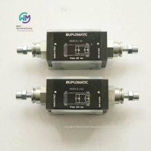
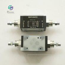
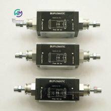
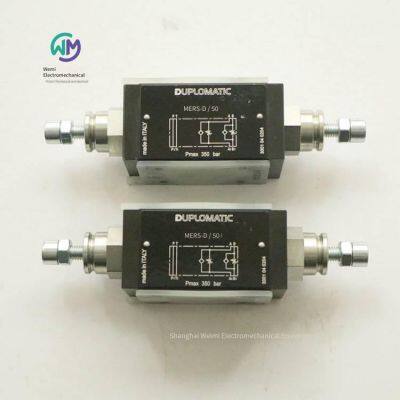
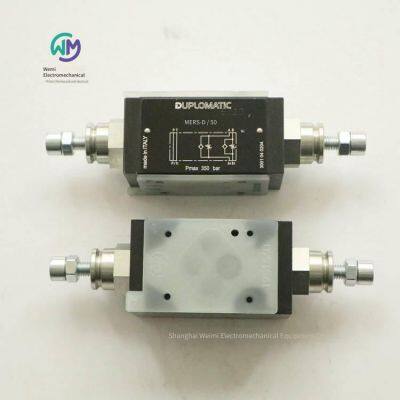
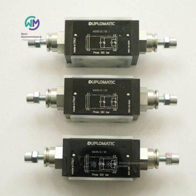
Italian Duplomatic Throttle Valve Mers-d/50
Related Products
-
 Rexroth Check Valve Z1s6t05-40/vUS$ 150.77 - 153.85MOQ: 1 Piece
 -
Rexroth Pressure Limiting Valve Dbds30g1a/200-170US$ 243.08 - 246.15MOQ: 1 Unit
-
Duplomatic Stacked Throttle Valve Mers-rd/50US$ 123.08 - 126.15MOQ: 1 Piece
-
Aventics Pneumatic Valve 5672310000US$ 376.92 - 384.62MOQ: 1 Piece
-
Aventics Solenoid Valve Body 0820022991US$ 141.54 - 146.15MOQ: 1 Piece
Italian DUPLOMATIC throttle valve MERS-D/50, the main product of Shanghai Weimi Mechanical & Electrical Equipment Co., Ltd. Sales hotline: 13524123009; Contact person: Lei Qing; Product real-shot pictures, original and genuine products, in-stock inventory, affordable prices. We sincerely welcome new and old customers to inquire and purchase!
Italian DUPLOMATIC throttle valve MERS
Stacked type
ISO 4401-03
High working pressure 350 bar
This valve is a stacked flow control valve without pressure compensation. The integrated check valve allows the oil to flow freely in the reverse direction. Its mounting surface size conforms to the ISO 4401 standard. This valve can be combined with other valves conforming to the CETOP 03 standard into a stacked valve group through bolts or screws without tubing connection.
This valve can also provide a reversible form (G* type). The choice between inlet throttling and outlet throttling depends on its installation direction on the mounting plate with O-rings.
All models of the valve are integrated with a check valve, allowing the oil to flow freely in the reverse direction (opening pressure 0.5 bar).
It is usually supplied with a hexagonal adjusting screw.
Structure
“SA”: Controls the flow of oil from the actuator into line A.
“SB”: Controls the flow of oil from the actuator into line B.
“D”: Controls the discharge flow of the two chambers of the actuator respectively. (Standard)
“RD”: Controls the input flow of the two chambers of the actuator respectively.
“G*”: Reversible valve.
Technical parameters (measured at an oil temperature of 50°C and an oil viscosity of 36 cSt)
Maximum working pressure 350 bar
Check valve opening pressure 0.5 bar
Maximum flow rate of the control line 50 l/min
Maximum flow rate of the free line 75 l/min
Minimum control flow rate at ∆p 10 bar ≤0.060 l/min
Ambient temperature range -20 / +50℃
Oil temperature range -20 / +80°C
Oil viscosity range 10 ÷ 400 cSt
Permissible pollution level of the oil According to ISO 4406:1999 grade 20/18/15
Recommended oil viscosity 25 cSt
Weight 1.3 kg
Hydraulic oil
When using mineral hydraulic oil HL or HM conforming to the ISO 6743-4 standard, use NBR seals. For HFDR oil (phosphate ester), use FPM seals (code V).
Ordering models of Italian DUPLOMATIC throttle valves:
MERS-RD/50
MERS-D/50
MERS-SA/50
MERS-SB/50
Italian DUPLOMATIC electromagnetic switching valves, MDS3 series
Stacked type
ISO 4401-03 (CETOP 03)
High working pressure: 350 bar
Large flow rate: 50 l/min
The valve MDS3 is used for multi-directional switching or pressure valve selection.
The oil passage holes pass through the entire valve body. Due to its special design, the valve MDS3 can be installed together with all stacked valves complying with the ISO 4401-03 (CETOP 03) standard.
The special connection in the valve parallel to the P - T - A - B oil passages makes it easy to implement different hydraulic principle structures and reduces the pressure drop to a low value.
Some DC models can choose the smooth commutation characteristic.
Technical parameters (measured at a temperature of 50°C and an oil viscosity of 36 cSt)
Maximum working pressure:
Oil ports P - A - B 350bar
Oil port T (DC type) 210bar
Oil port T (AC type) 140bar
Maximum flow rate at oil ports P - A - B 50l/min
Ambient temperature range -20 / +50°C
Oil temperature range -20 / +80°C
Oil viscosity range 10 ÷ 400 cSt
The maximum allowable pollution level of the oil is grade 20/18/15 according to ISO 4406:1999
Recommended oil viscosity 25 cSt
Weight:
Single solenoid valve 1,5kg
Double solenoid valve 2kg
Hydraulic oil
When using mineral hydraulic oil HL or HM complying with the ISO 6743-4 standard, use NBR seals (code N). For HFDR oil (phosphate ester), use FPM seals (code V). If using other oils, such as HFA, HFB, HFC, please consult our technical department.
When the working oil temperature is higher than 80 °C, it will cause the hydraulic oil and seals to age and deteriorate too quickly. Please pay attention to maintaining the stable physical and chemical properties of the hydraulic oil.
Smooth commutation
Currently, the smooth commutation characteristic can only be provided when the spool function of the DC valve is S12, SA12, and SB12.
This valve achieves smooth start and stop of the hydraulic actuator by reducing the movement speed of the spool. The commutation time and characteristic curve are affected by the viscosity of the working medium (which is affected by temperature). In addition, the commutation time will also vary due to the flow rate and working pressure of the valve.
In order to achieve the correct function of smooth commutation, it is necessary to ensure that the solenoid iron core is filled with oil. To achieve this, we recommend installing a back-pressure valve of 1 - 2 bar in the return oil pipe T.
Solenoid
The solenoid is usually composed of an iron core and a coil. The iron core is installed in the valve body in a threaded form and includes an armature that is immersed in oil and can move frictionlessly. The internal contact with the oil in the return oil pipeline ensures the heat dissipation effect.
The coil is fixed on the iron core through a threaded ring and can be rotated to adapt to the available installation space.
Current and power consumption of DC solenoid valves
The current and power consumption values of different models of DC coils. When powered by alternating current (50 or 60 Hz), it needs to be achieved through a rectifier circuit. You can use a "D" type plug with a bridge rectifier (see Catalog 49 000). However, the decrease in power limit needs to be considered.
Installation
This valve can be installed in any direction. The valve can be installed on a flat surface by screws or bolts.
If the flatness or roughness does not reach the required minimum value, oil leakage is likely to occur between the valve and the installation surface.
Electrical plug
Except for the K12 type provided together with the valve and the plug, the solenoid valve is provided without a plug. For coils with a K1 type standard electrical connection (DIN 43650), the plug can be ordered separately. For the K7 type connection form, the corresponding plug cannot be provided separately.
Ordering model of Italian DUPLOMATIC solenoid valve:
MDS3-SA1/10N-D24K1
MDS3-SA12/10N-D24K1/F
Italian DUPLOMATIC tube-type check valve VD*-W* series
Maximum working pressure: 400 bar
The tube-type check valve VD*-W* has "BSP" threaded oil ports and is suitable for installation in hydraulic pipelines.
This valve allows free flow of oil in the forward direction and prohibits flow in the reverse direction.
In the non-working state, the cone spool is kept closed by the spring. When the pressure at the oil inlet "A" is greater than the sum of the spring pressure value and the pressure value at the oil outlet "B", the cone spool opens.
Eight specifications are available, with a maximum flow rate of up to 850 l/min, and five different opening pressures can be provided.
Hydraulic oil
Use mineral hydraulic oil HL or HM that complies with ISO 6743-4 standard.
When the working oil temperature is higher than 80 °C, it will cause the hydraulic oil and seals to age and deteriorate too quickly.
Please pay attention to maintaining the stable physical and chemical properties of the hydraulic oil.
VD2-W* Oil port 1/4” Flow rate 25 l/min Weight 0,17kg Pressure 400bar
VD3-W* Oil port 3/8” Flow rate 40 l/min Weight 0,26kg Pressure 400bar
VD4-W* Oil port 1/2” Flow rate 75 l/min Weight 0,41kg Pressure 400bar
VD5-W* Oil port 3/4” Flow rate 125 l/min Weight 0,6kg Pressure 400bar
VD6-W* Oil port 1” Flow rate 200 l/min Weight 1,2kg Pressure 320bar
VD7-W* Oil port 1 ¼” Flow rate 280 l/min Weight 1,8kg Pressure 320bar
VD8-W* Oil port 1 ½” Flow rate 650 l/min Weight 3,2kg Pressure 320bar
VD9-W* Oil port 2” Flow rate 850 l/min Weight 4,8kg Pressure 320bar
Italian DUPLOMATIC digital electronic control unit, used for open-loop single solenoid proportional valve EDC-1
Technical parameters
Power supply voltage 10-30V DC - including fluctuation value
Required power Min. 20W - Max. 40W
Output current Min. 800mA - Max. 2600mA
Power supply electrical protection Overload over 33V, polarity reversal
Output electrical protection Short circuit
Analog electrical protection Up to 30 V DC
Available reference input signals
(Selectable via jumper)
0 - 10V Input impedance 100 kΩ
0 - 5V Input impedance 100 kΩ
4 - 20 mA Input impedance Max. 500 Ω
Plug type DIN 43650
Electromagnetic compatibility (EMC):
- Radiation CEI EN 61000-6-4
- Immunity CEI EN 61000-6-2
Degree of protection against ingress of solid objects and water (CEI EN 60529) IP 65 - 67
Operating temperature range -20/+70°C
Weight 0.1kg
The EDC-1 plug is a digital amplifier for controlling open-loop proportional valves. This unit provides a variable current proportional to the input signal, which is not affected by temperature changes or load impedance. The resolution of 2600 mA (full-scale value) reaches 1%.
The PWM characteristic of the electromagnet power supply reduces the hysteresis of the valve, thus optimizing the control accuracy. According to the controlled valve, the amplifier can be optimized and customized for various high-current specifications and switching frequencies (PWM).
Settings can be made through the buttons and display on the amplifier, or through an RS232 connection to a laptop using the EDC-PC software.
Function description
Power supply
The plug requires a power supply of 10 - 30 V DC (terminals 1 and 2).
Note: The power supply voltage of the plug must be higher than the rated operating voltage of the controlled electromagnet. The power supply voltage must be rectified and filtered, and the maximum allowable fluctuation is within the above voltage range.
The power required by the plug is determined by the power supply voltage value and the maximum supply current value (depending on the card model). Generally speaking, a safe value for the required power can be considered as the product of V x I.
For example: If the maximum current of the plug is 800 mA and the power supply voltage is 24 V DC, the required power is approximately 20W. If the maximum current of the card is 1600 mA and the power supply voltage is 24 VDC, the power used is equal to 38.5 W.
Electrical protection
The plug has functions to prevent overvoltage and polarity reversal. The output has short-circuit protection.
Reference input signal
The plug can accept 0 - 10V and 0 - 5V voltage reference input signals from an external generator (PLC, CNC) or an external potentiometer, as well as a 4 - 20 mA current signal.
Signal
Power supply indication (power)
The display indicates that the plug is in operation and is powered by +24 V DC.
Adjustment
There are two adjustment modes: parameter observation and parameter editing. The first mode can monitor each control value in real-time, including the required and readable current values in the two channels. The second mode can be used to observe and edit the operating parameters.
Parameter observation
When the card is switched to the parameter observation mode, the first changing parameter value displayed is U1 (input signal).
After pressing the button (1), the input current of the electromagnet is displayed. By pressing the button (1), different parameters can be switched. When each parameter is selected, its abbreviated name will appear for about one second. By briefly pressing the button, the current parameter name will be displayed for about one second.
Selectable parameters include:
U1: Reference input signal:
0 + 10V
0 + 5V
4 - 20mA (displayed as 2 - 10)
C1: Current required according to the input signal, in amperes, ranging from 0 to 2.6 A.
All the mentioned parameters can be observed from the two - digit display on the front panel of the plug.
Parameter editing
Press and hold key (2) for at least 3 seconds to enter the parameter editing mode. One of the displayed parameters is G1. To modify this parameter, press and hold key (1) for 2 seconds until the display flashes. Use key (2) to increase the value and key (1) to decrease the value. Press both keys simultaneously to save the new value. The display stops flashing.
Press key (2) to scroll through the parameters. If you need to modify other parameters, repeat the above steps for modifying parameter G1.
Selectable parameters include:
G1: "I Max" current, expressed in milliamperes.
This parameter sets the maximum current supplied to the electromagnet when the reference input signal is at its maximum value of +10 V (or 20 mA). This parameter is used to limit the maximum hydraulic size for valve control.
Default value = Imax
Range = 50 - 100% of Imax
o1: "I Min" current, expressed in milliamperes.
This parameter sets the bias current of the electromagnet when the reference input signal exceeds the limit of 0.1 V (or 0.1 mA). This parameter is used to eliminate the dead zone of the valve. Default value = 0% Range = 0 - 50% of Imax
u1: "Ramp Up" rise ramp time, in seconds.
This parameter sets the time for the current to increase when the input signal changes from 0 to 100%. This parameter is used to slow down the response time of the valve to prevent sudden changes in the input signal.
Default value = 00 seconds
Range = 00 - 50 seconds
d1: "Ramp Dn" fall ramp time, in seconds
This parameter sets the time for the current to decrease when the input signal changes from 100% to 0. This parameter is used to slow down the response time of the valve to prevent sudden changes in the input signal.
Default value = 00 seconds
Range = 00 - 50 seconds
Fr: PWM frequency, in Hertz. This parameter is used to set the pulsation frequency PWM of the control current. Decreasing the PWM can improve the accuracy of the valve but reduce the adjustment stability. Increasing the PWM can improve the adjustment stability but increase the hysteresis.
Default value = PWM (according to the card model)
Range = 50 - 500Hz
Error signal
EE: 4 - 20 mA cable breakage error signal (threshold 3 mA). Turn off the +24 V DC cable to reset the alarm.
Installation
The plug-in electronic unit can be directly installed on the solenoid of the corresponding proportional valve. The 4-core connection cable (single cable cross-sectional area 0.5 mm2) is pre-wired during supply, with a standard length of 2.5 m (DIN47100 standard).
Note 1 It is very important that the electrical connection of the control unit must comply with the wiring diagram to meet the EMC requirements. Generally, the wiring of the valve and the electronic unit must be kept as far away as possible from interference sources (such as power cables, motors, exchangers, and electrical switches).
In an environment with electromagnetic interference, the wiring must be fully protected.
Commissioning, control setting, and signal measurement
Setting device
The settings can be modified through the buttons (1) and (2) on the front panel of the card, or by using the EDC-PC hardware and software package.
EDC-PC software
Through the corresponding hardware and software package (to be ordered separately), the parameter values of the plug can be easily read and set.
The software communication is realized through a flat cable connected to the corresponding plug behind the protective cover on the EDC-1 panel. The EDC-PC is only guaranteed to be compatible with the Windows 2000 and Windows XP operating systems.
Ordering model of the Italian DUPLOMATIC amplifier board:
EDC-131/10E1
The Italian DUPLOMATIC digital amplifier is used for the open-loop proportional valve EDM-M* series
EDM-M1 single solenoid
EDM-M2 double solenoids
EDM-M3 two independent channels for two single solenoids
Rail-mounted form: DIN EN 50022
The EDM-M* type card is a digital amplifier for open-loop proportional valve control. Its design complies with the rail-mounted form: DIN EN 50022.
This unit provides a variable current proportional to the reference input signal, which is not affected by temperature changes or load impedance.
The PWM characteristic of the solenoid power supply reduces the hysteresis of the valve, thereby optimizing the control accuracy. This unit is available in three main forms, which can control single-solenoid valves (M1), double-solenoid valves (M2), and two single-solenoid valves with two independent channels (M3). Each form can be optimized and customized for various large current specifications and switching frequencies (PWM) according to the corresponding valve.
Parameter adjustment can be completed through the buttons and display on the front panel, or by connecting a laptop through an RS232 or USB converter (EDMPC/20 software).
Power supply voltage: 10 - 30 V DC including fluctuation value
Required power: Min. 20W - Max. 40W
Output current: Min. 800mA - Max. 2600mA
Power supply electrical protection: Overload when exceeding 33V, polarity reversal
Output electrical protection: Short circuit
Analog electrical protection: Up to 30V DC due to incorrect power connection
Available reference input signals
0 - 10V, input impedance 10 - 100 kΩ
±10V, input impedance 10 - 100 kΩ
4 - 20 mA, input impedance: Max. 500 Ω
Additional output port: ±10V DC to the power supply, 50 + 50 mA to the external potentiometer
Electromagnetic compatibility (EMC) according to 2004/108/CE standard
Enclosure material: Thermoplastic polyamide
Enclosure dimensions: 120 x 93 x 23mm
Plug: Plug-in terminal block with fastening bolts: 15 pins
Operating temperature range: -20 / +70°C
Mass: 0.15kg
Italian DUPLOMATIC amplifier board EDM-M*
Function description
Power supply
The power supply required for the amplifier board is between 10 and 30 V DC (terminals 1 and 2).
Note: The power supply voltage of the amplifier board must be higher than the rated operating voltage of the controlled electromagnet.
The power supply voltage must be rectified and filtered, and the maximum allowable fluctuation is within the above voltage range.
The power required by the card is determined by the power supply voltage value and the maximum supply current (depending on the card model). Generally speaking, a conservative value of the required power can be considered as the product of V x I.
For example: If the maximum current of the card is 800 mA and the power supply voltage is 24 V DC, the required power is approximately 20W. If the maximum current of the card is 1600 mA and the power supply voltage is 24 VDC, the power used is equal to 38.5 W.
Electrical protection
The amplifier board has the function of preventing overvoltage and polarity reversal.
The output terminal has short-circuit protection.
Reference input signals
The amplifier board can accept voltage reference input signals of 0 - 10 V and ± 10 V, as well as current reference input signal of 4 - 20 mA, provided by an external generator (PLC, CNC) or an external potentiometer powered by the card itself. The corresponding reference input values depend on the card model.
Signal
Power supply indication (Power)
Two red displays indicate the power supply of the card:
On - Power supply is normal; Off - No power supply
Blinking - Others
Amplifier board status output
The status of the amplifier board can be detected through the "Card status output" located at pin 9 (refer to zero power supply, pin 15), with a load impedance of 220 KΩ and a maximum current of 100 mA. If the card is working normally, the voltage at this pin is the same as the power supply; if the card malfunctions, the output voltage is zero.
Malfunctions include:
Low voltage (below 10V)
Short circuit
Coil not connected. If the output at pin 9 is too low, the control logic will disable the power output to the electromagnet. If the malfunction is resolved, the amplifier board will automatically restart.
Adjustment
There are two adjustment modes: parameter observation and parameter editing. The first mode can monitor each control value in real - time, including the required and readable current values in the two channels. The second mode can be used for observing and editing working parameters.
Parameter observation
When the amplifier board is switched to the parameter observation mode, the changing parameter value displayed is the reference
input signal of channel 1.
By pressing the keys (+) and (-), different parameters can be switched. When a parameter is selected, its abbreviated name will appear for about one second.
By briefly pressing the key (E), the current parameter name will be displayed for about one second.
The selectable parameters include:
U1: Channel 1 reference input signal: 0 + 9.9V for single electromagnet 4 - 20 mA; - 9.9/0/+9.9 V for double electromagnets 4/12/20 mA
C1: According to the input signal, the current required by channel 1, in amperes, ranging from 0 to 3.0 A.
E1: The actual current provided by channel 1, in amperes, ranging from 0 to 3.0 A.
U2: Channel 2 reference input signal: 0 + 9.9V for single electromagnet 4 - 20 mA; - 9.9/0/+9.9 V for double electromagnets 4/12/20 mA
C2: According to the input signal, the current required by channel 1, in amperes, ranging from 0 to 3.0 A.
E2: The actual current provided by channel 2, in amperes, ranging from 0 to 3.0 A.
All the mentioned parameters can be observed from the two - digit display on the front panel of the plug.
Parameter editing
Press and hold the key (-) for more than 1.5 seconds to switch from the parameter observation mode to the parameter editing mode, and vice versa.
In the parameter editing mode, as in the previous mode, different parameters can be switched by briefly pressing the keys (+) and (-). When a parameter is selected, its abbreviated name will appear for about one second. By briefly pressing the key (E), the current parameter name will be displayed for about one second. Press and hold the key (E) for more than 1.5 seconds, the parameter name will blink for about one second: by pressing the keys (+) and (-), the parameter value can be modified. Whenever one of these keys is pressed, the corresponding value increases or decreases by one unit; if the key is held down, the value can continue to increase.
Once the editor obtains the required value, exit by pressing the button (E). At this time, the value is stored in the EEPROM, and the buttons (+) and (-) resume their parameter selection function. Once the parameterization cycle is completed, hold down the button (+) for more than 2 seconds until the display starts to flash. All parameters will be stored in the EEPROM, and it will return to the parameter observation mode.
Selectable parameters include:
G1: “I Max” current, expressed in milliamperes.
This parameter sets the maximum current supplied to the electromagnet of channel 1 when the reference input signal is at its maximum value of +10 V (or 20 mA). This parameter is used to limit the maximum hydraulic size for valve control.
o1: “I Min” current, expressed in milliamperes.
This parameter sets the bias current of the electromagnet of channel 1 when the reference input signal exceeds the limit of 0.1 V (or 0.1 mA). This parameter is used to eliminate the dead zone of the valve.
Range = 0 - 50% of I Max
r1: “Max Ramp” - Ramp time, in seconds. When the reference input signal changes from zero to 100%, this parameter sets the time required for the current supplied to channel 1 to change from zero to the maximum value, and vice versa. This parameter is used to slow down the response time of the valve to prevent sudden changes in the input signal.
Range = 00 - 20 seconds
u1: “Ramp Up” - Rising ramp time, expressed as a percentage of the ramp time r1. This parameter sets the time for the current of channel 1 to increase when the input signal changes from 0 to 100%.
Default value = 99%
Range = 00 - 99%
d1: “Ramp Dn” - Falling ramp time, expressed as a percentage of the ramp time r1. This parameter sets the time for the current of channel 1 to decrease when the input signal changes from 100% to 0.
Default value = 99%
Range = 00 - 99%
G2: “I Max” - Current, expressed in milliamperes.
This parameter sets the maximum current supplied to the electromagnet of channel 2 when the reference input signal is at its maximum value.
o2: “I Min” - Current, expressed in milliamperes.
This parameter sets the bias current of the electromagnet of channel 2.
Range = 0 - 50% of I Max
r2: “Max Ramp” - Ramp time, in seconds. When the reference input signal changes from zero to 100%, this parameter sets the time required for the current supplied to channel 2 to change from zero to the maximum value, and vice versa. This parameter is used to slow down the response time of the valve to prevent sudden changes in the input signal.
Range = 00 - 20 seconds
u2: "Ramp Up" rising ramp time, expressed as a percentage of the ramp time r2. This parameter sets the time for the current of channel 2 to increase when the input signal changes from 0 to 100%.
Default value = 99%
Range = 00 - 99%
d2: "Ramp Dn" falling ramp time, expressed as a percentage of the ramp time r2. This parameter sets the time for the current of channel 2 to decrease when the input signal changes from 100% to 0.
Default value = 99%
Range = 00 - 99%
Fr: "PWM Freq" - PWM, unit Hertz. This parameter is used to set the pulsation frequency PWM for controlling the current. Reducing the PWM can improve the accuracy of the valve but will reduce the adjustment stability. Increasing the PWM can improve the adjustment stability but will increase the hysteresis.
Default value = PWM (according to the card model)
Range = 50 - 400Hz
U1 and U2: This parameter represents the set range.
Through this parameter (can only be modified through software), even if the setting is lower than 10V, the same resolution can still be maintained.
For example: Card EDM-M121, with a 10V command and standard parameter setting, the output current range is 1200 mA. If the setting value of "U" is 500, the output current range is 600
mA.
If the card is set for a single solenoid valve, only the parameters of channel 1 can be observed.
Installation
This card is designed for rail-mounted installation, conforming to the DIN EN 50022 form. Wiring is completed through the terminal block, which is located at the bottom of the electronic control unit. Cables with a cross-sectional area of 0.75 mm2 and a length of up to 20 m and cables with a cross-sectional area of 1.00 mm2 and a length of up to 40 m are recommended for power supply and solenoid connections. For other connections, it is recommended to use cables with a shielded sheath, and only the card side should be grounded.
Ordering models of DUPLOMATIC amplifier boards from Italy:
EDM-M212/30E1-B
EDM-M231/30E0-B
EDM-M31111/30E0-A
EDM-M31111/30E0-B
EDM-M31122/30E0-B
EDM-M212/30E0-B
EDM-M212/30E1-B
EDM-M231/31E0-B
DUPLOMATIC electronic control unit from Italy
For open-loop single solenoid proportional valve amplifier board
UEIK-1* series
Technical parameters
Power supply: 22 - 30VDC
Power supply electrical protection: Overload, Polarity reversal
Reference input signal:
Voltage: 0 / +10 V
Current: 4 - 20mA
Reference input signal impedance
Voltage: 10kΩ
Current: 250Ω
Card size: Eurocard format 100x160x35
Plug interface: DIN 41612-D 32 external thread
Operating temperature range: 0 - 50℃
Weight: 0.2kg
The UEIK-1* type card is a Eurocard format electronic control unit for open-loop single solenoid proportional valves. This unit provides a variable current proportional to the reference input signal, which is not affected by temperature changes or load impedance.
The PWM characteristic of the solenoid power supply reduces the hysteresis of the valve, thereby optimizing the control accuracy. The front panel is equipped with LED lights, which can display the functions of the card and the potentiometer, thus optimizing the control.
Function description
Power supply
The power supply required for the card is between 22 and 30 V DC (pins 2a/2c - 4a/4c), and the required power is: 20W (UEIK-11) - 29W (UEIK-12).
The power supply voltage must be rectified and filtered, and the maximum allowable fluctuation is within the above voltage range.
Electrical protection
The card has the functions of preventing overvoltage and polarity reversal.
A 2A fast-blow fuse is installed for power circuit protection.
Reference input signal
This card can accept a voltage reference input signal (0 to +10V) or a current reference input signal (4 - 20 mA).
Note: If the signal is emitted by a potentiometer, please verify that its load is at least 200 Ω.
Signal and adjustment
Power POWER ON
The yellow LED light indicates the power status of the card:
On - Power is normal
Off - No power, power failure or fuse blown
Enable ENABLE
The card needs an enable signal of 22 to 30 V DC applied at pin 24c to work normally.
The enable status of the card can be observed through the LED light on the front panel or measured by the user at pins 6a and 6c.
The green LED light indicates:
On - Card is turned on
Off - Card is turned off or there is a fault
Gain GAIN (Gain coefficient adjustment)
The gain potentiometer "GAIN" can adjust the relationship between the set reference signal value and the large current supplied to the electromagnet, thus used to limit the maximum hydraulic size for valve control.
The maximum current of the card is limited to 1.0A (UEIK - 11) - 1.2A (UEIK - 12). See the default values in Section 6.
Rotate clockwise to increase the current.
Offset OFFSET (Offset current adjustment)
The offset potentiometer "OFFSET" can adjust the offset current of the valve. This parameter is used to eliminate the insensitive area (dead zone) of the valve.
The adjustment range is from 0 to 0.5A (UEIK - 11) - from 0 to 0.65A (UEIK - 12).
When the reference input signal exceeds the threshold of + 150 mV (or 4.25 mA), the offset current is activated.
Below this threshold, the offset is not activated, and it only occurs when the polarization current is equal to 25 mA.
Note: A change in the offset current setting value will cause a corresponding change in the gain coefficient value.
Rotate clockwise to increase the current.
Ramp Up / Ramp Down (Ramp adjustment)
The ramp - up potentiometer "RAMP UP" and the ramp - down potentiometer "RAMP DOWN" can adjust the time required to reach the required supply current when the corresponding reference input signal has a step - up or step - down change, ranging from 0.03 to 7 seconds.
In this way, the response time of the valve can be controlled, so as to adjust the valve to meet the requirements of the hydraulic circuit and the machine cycle.
The ramp can be disabled by applying a disconnection command of 22 to 30 V DC at pin 16a. In this case, the remaining ramp time is 10 ms.
Rotate clockwise to increase the ramp time.
Signal measurement
Current CURRENT (Electromagnet current measurement point)
The current supplied to the electromagnet can be read through voltage.
Reading conversion:
1V DC = 1A (UEIK - 11)
0.82V DC = 1A (UEIK - 12).
Reference signal REFERENCE (Reference input signal measurement point)
The reference input signal sent to the card can be read through voltage.
Read directly, but the sign between the reference voltage and the current is opposite, and the conversion is:
4 mA = 0 V 20 mA = - 10V.
Installation
The card can be installed in a bracket or a card rack, and its interface form is DIN 41612 - Specification D - 32 pins.
For the connection between the power supply and the electromagnet, it is recommended to use wires with a cross-sectional area between 1 and 2.5 mm² according to the length. For other connections, it is recommended to use cables with a shielded sheath, and only the card side should be grounded.
Generally, the wiring of valves and electronic units must be kept as far away as possible from interference sources (such as power cables, motors, exchangers, and electrical switches).
In an environment with electromagnetic interference, the wiring must be fully protected.
Default state
The electronic unit is factory-set when supplied.
The standard settings are as follows:
“GAIN” gain adjustment: When the reference input signal is +10V (or 20 mA), the corresponding electromagnet input current is 0.7 A.
– “OFFSET” offset adjustment: Zero
– “RAMP UP” rising ramp and “RAMP DOWN” falling ramp adjustment: Small value
– SW1 is in position V
– SW2 is in position S
– SW3 is in position AA
– Switching frequency (PWM) =
200Hz (UEIK - 11)
100Hz (UEIK - 12).
Commissioning and control settings
If necessary, the settings can be modified as follows:
a) Offset current adjustment
– Set the gain potentiometer “GAIN” to the minimum value.
– Input the maximum reference input signal value (+10V or 20 mA).
– Set the offset potentiometer “OFFSET” so that the valve is positioned in the starting working area.
b) Gain coefficient adjustment
– Input the maximum reference input signal value (+10V or 20 mA)
– Set the gain potentiometer “GAIN” so that the controlled hydraulic parameter reaches the required maximum value.
c) Ramp adjustment
– Adjust the rising ramp potentiometer “RAMP UP” and the falling ramp potentiometer “RAMP DOWN” so that the valve opens gradually when the reference input signal changes.
Circuit settings of the card
Each operation of modifying the switch settings must be carried out when the card is powered off. The independent switches in each module must be set to the same position.
Selection of voltage or current reference input signal
(The SW 1 module consists of three independent switches)
– Select V for voltage reference input signal
– Select I for current reference input signal
Selection of single-ended reference input signal or differential reference input signal
(The SW 2 module includes an independent switch)
– Select S for single-ended reference input signal. This state is mandatory when the external potentiometer that generates the reference input signal is powered by the card itself.
– Select D for the differential reference input signal. When the reference input signal comes from the analog output of the PLC or CNC, this state is preferentially selected.
Note: The SW 3 module consists of two independent switches. In the standard default state, it must always be set to the AA state.
Switching frequency adjustment
The switching frequency (PWM) can be modified by the adjuster PT7 (see Section 10).
The setting range is from 80 to 370 Hz.
Appropriate adjustment of the switching frequency can reduce the hysteresis value of the valve.
Rotate clockwise to increase the frequency.
Italian DUPLOMATIC proportional valve amplifier board
UEIK-11/51-24
UEIK-12/51-24
Italian DUPLOMATIC throttle valve MERS-D/50

Send Inquiry to This Supplier


You May Also Like
-
Rexroth Piston Pump Aa10vso28dfr/31r-ppa12n00US$ 1092.31 - 1307.69MOQ: 1 Piece
-
Rexroth Pressure Relief Valve Dbdh6g1x/400US$ 138.46 - 146.15MOQ: 1 Piece
-
Rexroth Proportional Valve Amplifier Board 0811405104US$ 638.46 - 653.85MOQ: 1 Piece
-
Aventics Pull Rod Cylinder 0822343004US$ 187.69 - 190.77MOQ: 1 Piece
-
Aventics Filter Pressure Regulator R412009210US$ 212.31 - 215.38MOQ: 1 Piece
-
German Aventics Valve Island R480034030US$ 938.46 - 953.85MOQ: 1 Piece
-
Rexroth Pressure Reducing Valve Zdr6dp2-4x/25ymUS$ 146.15 - 150.77MOQ: 1 Piece
-
Rexroth Stacked Pressure Reducing Valve Zdr6dp2-43/210ymUS$ 104.62 - 107.69MOQ: 1 Piece
-
Aventics Air Distribution Block R412006251US$ 32.31 - 33.85MOQ: 2 Pieces
-
Aventics Pilot Valve 1827414004US$ 61.54 - 64.62MOQ: 1 Piece


