

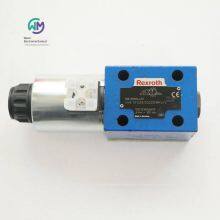
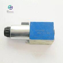
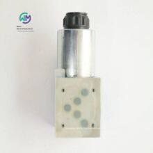
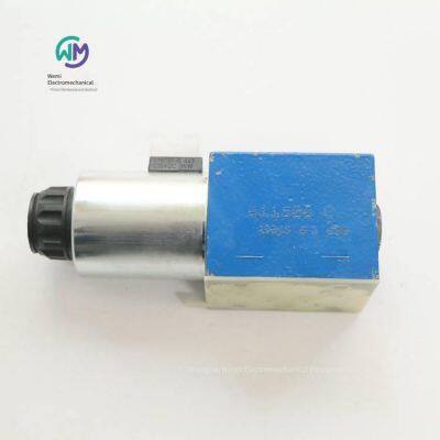
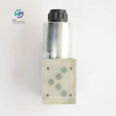
Rexroth Dc220v Solenoid Valve 4we10d33/cg220n9k4/v

Related Products
-
 Aventics Air Source Shut - off Valve 0821300913US$ 53.85 - 55.38MOQ: 1 Piece
 -
Rexroth Proportional Relief Valve 0811402016 Dbetx-10/315g24-8nz4mUS$ 369.23 - 384.62MOQ: 1 Piece
-
Duplomatic Gear Pump Gp20140r95b20nUS$ 353.85 - 369.23MOQ: 1 Unit
-
Rexroth Proportional Cartridge Valve 0811402622 Fesxe40ca-1x/500lk0b1mUS$ 2769.23 - 2846.15MOQ: 1 Piece
-
Italian Duplomatic Gear Pump Gp20113r97f20nUS$ 369.23 - 376.92MOQ: 1 Unit
Rexroth DC220V solenoid valve 4WE10D33/CG220N9K4/V, the main product of Shanghai Weimi Mechanical & Electrical Equipment Co., Ltd. Sales hotline: 13524123009; Contact person: Lei Qing; Real-shot product pictures, original genuine products, in-stock inventory, affordable prices; We sincerely welcome new and old customers to consult and purchase!
Rexroth REXROTH direct-acting directional spool valve with electromagnetic actuation
WE 10...E
Size 10
Component series 5X
Maximum working pressure 350 bar
Maximum flow rate 160 l/min
Three-position four-way, two-position four-way or two-position three-way models
Port mounting surface complies with ISO 4401-05-04-0-05
High-power coil, optional 90° rotation
Electrical connection as single or centering connection
Optional to be used with PWM connector (fast switching amplifier, energy-saving)
Optional auxiliary operating device
When the voltage is > 50 VAC or > 75 VDC, CE compliance meets the Low Voltage Directive 2014/35/EU
The electromagnetic coil is an approved component with UR mark, optional
Optional to be certified by CSA C22.2 139-13
The directional valve of the WE model is an electromagnetic coil-operated directional spool valve, and this valve can be used as an electromagnetic component. This valve controls the start, stop and direction of the fluid.
The basic structure of this directional valve consists of a housing, one or two electromagnets, a control spool and a return spring. In the power-off state, the control spool is held in the middle position or the initial position (except for version "O") by the return spring. When the electromagnet in the hydraulic oil is energized, the control spool moves from its rest position to the desired end position. In this way, the desired fluid direction can be issued according to the selected symbol.
After the electromagnet is turned off, the control spool will be pushed back to the middle position or the initial position (except for valves with "OF" device and valves without spring type "O").
The auxiliary operation can manually switch the valve when the magnet is not energized.
The hydraulic system must be properly ventilated to ensure normal function.
Without spring return "O" (only applicable to symbols A, C and D)
This model is a directional valve with two switching positions and two electromagnets without a device. The valve without spring return at the control spool has no definite initial position in the power-off state.
Without spring return, with device "OF" (only applicable to symbols A, C, and D)
This model is a directional valve with two switch positions, two electromagnets, and a device. The control spool is fixed in the corresponding switching position by the device. Therefore, during operation, there is no need to apply current to the electromagnets, which helps with energy-saving operation.
Model "73...A12" (soft switching behavior)
The combination of the control spool and the electromagnetic coil reduces the number of commutation strokes that occur when the valve opens or closes.
Compared with standard valves, the commutation stroke (measured as the acceleration value a) can be reduced by approximately 85%, depending on the model of the control spool (see "Acceleration value").
Note:
Pressure peaks in the drain lines connecting two or more valves may cause unexpected movement of the control spool in models with a device. It is recommended to lay separate return lines or install check valves in the drain lines.
Due to the design principle, internal leakage will occur in the valve, and the leakage amount will increase during the service life.
Throttle plug-in
According to the main working conditions, if the flow rate may exceed the performance limit of the valve during the switching process, a throttle plug-in will be required.
Order numbers and models of German Rexroth electromagnetic directional valves:
R900944371 4WE10D33/CG220N9K4/V
R901487117 4WE10C50/EW230N9K4/M
R900598925 4WE10D33/CW110N9K4
R900912496 4WE10D33/CW230N9K4
R900923393 4WE10D33/CW230N9K4/V
R901336181 4WE10D50/EG205N9K4/M
R901344560 4WE10D50/EG220N9K4/V
R901339383 4WE10D50/EG220N9K4/M
R901278760 4WE10D50/EG24N9K4/M
R901483529 4WE10D50/EW230N9K4/M
R901391200 4WE10D50/HG24N9K4/M
R901344562 4WE10D50/OFEG220N9K4/M
R901278763 4WE10D50/OFEG24N9K4/M
R901278761 4WE10E50/EG24N9K4/M
R901390857 4WE10E50/HG24N9K4/M
R900595532 4WE10EA33/CG24N9K4
R901278780 4WE10EB50/EG24N9K4/M
R901278768 4WE10G50/EG24N9K4/M
R901427832 4WE10G50/HG24N9K4/M
R900597986 4WE10H33/CG24N9K4
R901349517 4WE10HB50/EG24N9K4/M
R900593805 4WE10J33/CW230N9K4
R901278744 4WE10J50/EG24N9K4/M
R901401552 4WE10J50/HG24N9K4/M
R901327207 4WE10J50/EG205N9K4/M
R901278782 4WE10JA50/EG24N9K4/M
R901278784 4WE10R50/EG24N9K4/M
R901349519 4WE10RB50/EG24N9K4/M
R901333735 4WE10T50/EG24N9K4/M
R901391202 4WE10Y50/HG24N9K4/M
R900591664 4WE10D3X/OFCG24N9K4
R901391203 4WE10C51/HG24N9K4/M
R901391200 4WE10D51/HG24N9K4/M
R901390857 4WE10E51/HG24N9K4/M
R901427832 4WE10G51/HG24N9K4/M
R901427828 4WE10H51/HG24N9K4/M
R901427828 4WE10H52/HG24N9K4/M
R901401552 4WE10J51/HG24N9K4/M
R901391161 4WE10L50/HG24N9K4/M
R901278778 4WE10U50/EG24N9K4/M
Rexroth Pilot-operated proportional directional valves with integrated electronics (OBE) and electrical position feedback
4WRKE
Specifications: 10, 16, 25, 27, 32, 35
Component Series: 3X
Maximum Working Pressure: 350 bar
Maximum Flow Rate: 3000 l/min
Pilot-operated two-stage proportional directional valve with electrical position feedback of the main control spool and integrated electronics (OBE)
Adjust the direction and magnitude of the volumetric flow rate
Operated by proportional solenoids
For subplate mounting: Hole pattern according to ISO 4401
Electrical position feedback
Spring-centered main control spool
Pilot control valve: Single-stage proportional directional valve
Main stage with position control
Pilot control valve (first stage) of type 4WRAP 6 W7.3X/G24…
The pilot control valve is a direct-acting proportional valve. The geometry of the control edges is optimized and can be used as the pilot control valve for the proportional directional valve model 4WRKE. The proportional solenoids are pressure-tight, hermetically sealed wet-pin DC coils with removable coils. They can convert the current into mechanical force in proportion. An increase in the current will cause a corresponding increase in the magnetic force of the coil. The set magnetic force of the coil will remain constant throughout the control stroke.
The pilot control valve mainly consists of a housing, proportional solenoids, a control spool, and springs. In the non-operating condition, both actuators are connected to the oil tank. If one of the two coils is energized, the magnetic force will move the control spool of the valve towards the spring. Once the overlap is exceeded, the connection between one of the two actuators and the oil tank will be blocked, and instead, it will be connected to the pressure chamber. The fluid flows from P to the control chamber of the main stage.
Valves of type 4WRKE are two-stage proportional directional valves. They control the flow direction and flow rate. The main stage is position-controlled, so that the position of the control spool will not be affected by the hydraulic force even under a large flow rate.
This type of valve mainly consists of a pilot control valve, a housing, a main control spool, a cover, a centering spring, an inductive position sensor, and a pressure reducing valve. If there is no input signal, the main control spool will be fixed in the center position by the centering spring. The two control chambers in the cover are connected to the oil tank through the control spool. The main control spool is connected to the appropriate control electronics through the inductive position sensor. Both the change in the position of the main control spool and the change in the control value at the summing point of the amplifier can generate a differential voltage. During the comparison of the control value and the theoretical value, the possible control deviation is determined by the electronics, and a current is applied to the proportional solenoid of the pilot control valve. The current will generate a force in the coil that continuously operates the control spool through the push rod. The flow rate activated through the control profile will cause the adjustment of the main control spool. The main control spool connected to the core of the inductive position sensor will keep moving until the theoretical value matches the control value. In the control state, the main control spool is in a force balance state and stays at this control position. The stroke of the control spool and the control opening change proportionally to the control value. The control electronics are integrated into the valve. By adjusting the valve and the electronics, the deviations caused by mass-produced equipment can be kept at a low level.
Do not let the fuel tank pipeline run empty; under the corresponding installation conditions, a preload valve (with a preload pressure of approximately 2 bar) must be installed.
Valve Features
The basic setting of the secondary valve includes our proportional valve module. The zero-potential adjustment of the "main stage zero potential" is preset at the factory and can be adjusted within ±30% of the nominal stroke through the potentiometer in the control electronics. The integrated control electronics can be serviced only after removing the protective plug in front of the cover housing. The replaced pilot control valve or control electronics must be readjusted. All adjustment work can only be performed by professional personnel.
Attention!
Changing the zero potential may cause system damage, so it can only be performed by professional personnel!
Order numbers and models of German Rexroth proportional valves:
R900757868 4WRKE10W6-100L-3X/6EG24EK31/F1D3M
R900704916 4WRKE16E200L-3X/6EG24ETK31/A1D3M
R900751112 4WRKE16W8-125L-3X/6EG24EK31/F1D3M
R900711320 4WRKE16W8-200L-34/6EG24ETK31/A1D3M
R900704397 4WRKE16W8-200L-3X/6EG24K31/A5D3M
R901396450 4WRKE16W8-200L-3X/6EG24K31/F1D3V
R901004332 4WRKE16E1-200L-35/6EG24ETK31/A1D3M
R901087600 4WRKE16R3-200P-35/6EG24ETK31/F1D3M
R901129810 4WRKE16W6-125L-3X/6EG24K31/F1D3V
R900743953 4WRKE25W8-350L-3X/6EG24ETK31/F1D3M
R901072883 4WRKE27W8-500L-3X/6EG24K31/F1D3M
Rexroth direct-acting high-frequency directional valve with electrical position feedback and integrated electronics (OBE)
4WRPEH 6
Size 6
Component series 3X
Maximum working pressure 350 bar
Nominal flow rate 4 … 40 l/min
Digital interface IO-Link for I4.0
Reliable - A proven and robust design
Safe - The fail-safe position of the control spool is closed
Energy-saving - No pilot oil is required
High quality - Control spool and sleeve with servo valve performance
Flexible - Suitable for position, rate and pressure control
- High response sensitivity and low hysteresis
IO-Link interface, optional
The 4WRPEH type valve is a direct-acting directional control valve with electrical position feedback and integrated electronics (OBE).
Structure
The 4WRPEH high-frequency response valve mainly includes:
Valve housing with control spool and sleeve with servo performance
Control coil with position sensor (optional electronic component protective film)
Integrated electronics (OBE) with analog or IO-Link interface (optional damping plate)
Function
The integrated electronics (OBE) compares the control value with the actual position value. In case of a control deviation, the stroke coil will be activated. Due to the change in the coil magnetic force, the control spool will adjust against the spring. The stroke/control spool cross-section is controlled in a manner proportional to the control value. When the preset control value is 0, the electronics adjusts the control spool against the spring to the center position. In the deactivated state, the spring is in a relaxed state, at this time the spring length is long, and the valve is in the fail-safe position.
Control coil cut-off
In the following fault conditions, the integrated electronics (OBE) de-energizes the control coil, and the control spool will be set to the fail-safe position:
Below the minimum power supply voltage
Only when the interface is "F1":
The current value is below the minimum current control value of 2 mA (including cable interruption of the control value line (current loop))
Only when the interface is "L1":
Enable is not activated, communication is interrupted (watchdog)
When an internal IO-Link fault occurs
Only when the interface is "C6":
Extra release is not activated
Damping plate "D"
The damping plate reduces the acceleration amplitude on the integrated electronics (frequency >300 Hz).
Note:
For applications with mainly low excitation frequencies (
Electronic component protective film "-967"
To protect against condensation in the housing of the integrated electronics (OBE), an electronic component protective film can be used.
It is recommended for use in external industrial standard conditions (such as outdoors) with high air humidity and significant periodic temperature changes.
Material numbers and models of German Rexroth proportional valves:
R901382315 4WRPEH6C3B40L-30/M/24A1
R901382350 4WRPEH6C3B40L-30/M/24F1
R901382312 4WRPEH6C3B12L-31/M/24A1
R901382315 4WRPEH6C3B40L-31/M/24A1
R901382350 4WRPEH6C3B40L-31/M/24F1
0811404601 4WRPEH6C3B12L-20/G24K0/A1M
0811404602 4WRPEH6C3B24L-20/G24K0/A1M
R901382313 4WRPEH6C3B24L-3X/M/24A1
0811404611 4WRPEH6C4B12L-20/G24K0/A1M
0811404612 4WRPEH6C4B24L-2X/G24K0/A1M
0811404613 4WRPEH6C4B40L-20/G24K0/A1M
0811404721 4WRREH6VB24L-11/G24K0/B5M
0811403001 4WRP10EA63S-1X/G24Z4/M
0811403559 4WRPNH6C3B04L-2X/M/24PF6G
R901412522 4WRPEH6C4B12L-31/M/24A1-561
R901382372 4WRPEH6CB24L-30/M/24F1
Rexroth direct-acting high-frequency directional valve with electrical position feedback and integrated electronics (OBE)
4WRPE10
Size 10
Component series 3X
Maximum working pressure: 350 bar
Nominal flow rate: 50 … 80 l/min
Digital interface IO-Link for I4.0
Reliable - Proven and robust design
Energy-saving - No pilot oil required, low pressure difference at high flow rate
Flexible - Suitable for position and speed control
- High response sensitivity and small hysteresis
Safety - The second coil can be cut off with the help of an ISA adapter.
IO-Link interface, optional
Three-position four-way directional valve
The 4WRPE type valve is a direct-acting directional control valve with electrical position feedback and integrated electronics (OBE).
Structure
The basic components of the valve include:
Valve body
Control spool with compression spring
Control coil with position sensor (optional with electronic component protective film)
Stroke coil
Integrated electronics (OBE) with analog interface or IO-Link interface (optional with damping valve plate)
Function
The integrated electronics (OBE) compares the control value with the actual position value. In case of a control deviation, the relevant coil will be activated. Due to the change in magnetic force, the control spool will be adjusted against the corresponding spring. The stroke/control spool section is controlled in a manner proportional to the control value. When the preset control value is 0 V, the electronics will adjust the control spool to the center position.
Error detection
If the following error conditions occur, the electronics will de-energize the control coil:
Below the minimum power supply voltage ≤ 15 V (restart ≥ 17.5 V).
Only at interface "F1":
Below the minimum current control value of 2 mA (including cable interruption of the control value line (current loop)).
Only at interface "L1":
Enable not activated, communication interrupted
When an internal IO-Link fault occurs
Only at interface "C6":
Additional enable not activated
The control spool is held in the mechanical center position by the compression spring ((with symbol V) not applicable to the hydraulic center position).
Damping valve plate "D"
The damping valve plate reduces the acceleration amplitude on the integrated electronics (frequency >300 Hz).
Note:
For applications with mainly low excitation frequencies (
Electronic component protective film "-967"
To protect against condensation in the housing of the integrated electronics (OBE), an electronic component protective film (8) can be used.
It is recommended for external industrial standard conditions with high air humidity and significant periodic temperature changes (e.g. outdoors).
Two-position four-way directional valve
The 4WRPE type valve is a direct-acting directional control valve with electrical position feedback and integrated electronics (OBE).
Structure
The basic components of the valve include:
Valve body
Control spool with compression spring
Control coil with position sensor (optional electronic component protective film)
Integrated electronics (OBE) with analog interface or IO-Link interface (optional damping valve plate)
Function
The integrated electronics (OBE) compares the control value with the actual position value. In case of a control deviation, the control coil is activated. Due to the change in magnetic force, the control spool is adjusted against the corresponding spring. The stroke/control spool cross - section is controlled in a way proportional to the control value. When a positive control value is preset, the valve opens from P to B or from A to T. During negative control, the position of the control spool remains unchanged.
Error detection
If the following error conditions occur, the electronics will de - energize the control coil:
Below the minimum supply voltage ≤ 15 V (restart ≥ 17.5 V).
Only at the interface "F1":
Below the minimum current control value of 2 mA (including cable interruption of the control value line (current loop)).
Only at the interface "L1":
Enable not activated, communication interrupted
When an internal IO - Link fault occurs
Only at the interface "C6":
Additional enable not activated
Damping valve plate "D"
The damping valve plate reduces the acceleration amplitude on the integrated electronics (frequency >300 Hz).
Note:
For applications with mainly low excitation frequencies (
Electronic component protective film "-967"
To protect against condensation in the housing of the integrated electronics (OBE), an electronic component protective film can be used.
It is recommended for external industrial standard conditions with high air humidity and significant periodic temperature changes (e.g. outdoors).
Order numbers and models of REXROTH proportional valves from Germany:
0811404766 4WRPE10CB80L - 20/G24K0/F1M - 810
0811404771 4WRPE10E80SJ - 20/G24K0/A1M
REXROTH pilot - operated high - frequency directional valve with electrical position feedback and integrated electronics (OBE)
4WRTE
Size 10 … 35
Component series 4X
Maximum working pressure: 350 bar
Maximum flow rate: 3000 l/min
Rated flow rate: 25 … 1000 l/min
Reliable - Proven and robust design
Safety
- Automatic pressure compensation in the main control chamber, achieved by means of a pilot control valve
- The main control spool is in the spring-centered position and/or offset position
- Optional spool position monitoring
Flexible - Suitable for position, rate and pressure control
- High response sensitivity and low hysteresis
The 4WRTE type valve is a pilot-operated directional control valve with electrical position feedback, integrated electronics (OBE) and optional spool position monitoring.
Configuration
The basic valve consists of 3 main components:
A housing with a main control spool and optional spool position monitoring
Integrated electronics with a main inductive position sensor (optional electronic component protective film)
A pilot control valve with a control spool/socket device, an inductive position sensor and pressure feedback at the center position of the main control spool
Function
After the proportional solenoid is de-energized, the main control spool will be held in the center position by the centering spring and pressure feedback
The main control spool is controlled by the pilot control valve → The main control spool is in the adjusted position
The control spool of the pilot control valve is controlled by changing the magnetic force of the coil of the proportional solenoid
Connection between the control value and the theoretical value of the integrated electronics
The pilot oil can be supplied to the pilot control valve internally through port P or externally through port X. The return oil of the pilot oil is drained to the tank internally through port T or externally through port Y
When the control value is 0 V, the electronics control the main control spool in the center position.
Spool position monitoring
The spool position of the main control spool is detected by a position sensing switch and then displayed through two switching outputs with preset logic. If the fixed set switching point is exceeded, the deviation from the zero position will be monitored in the control spool cover (see "Accessories").
These switching signals can be used in the advanced control for monitoring functions. The electrical connection is made separately through a 4-pole connector M12x1 with two signal output pins and two power supply pins.
Application fields
The valve can be used in safety-related dual-channel applications (Category 3, PL d and Category 4, PL e according to EN *********standard), such as a closing element for one channel. The valve meets the safety start-up and shutdown requirements of stop category 0 in EN 60204 standard.
If safety requirements are needed, the power supply voltage of the valve must be safely cut off based on
the required safety level (Category PL).
According to the application and working equipment requirements - in line with the specific standards of EN 13849-1, the user must provide
the appropriate monitoring/credibility check that meets the required diagnostic range DCavg and uses advanced control.
Electronic component protective film “-967”
To protect the condensation format in the integrated electronic component (OBE) housing, an electronic component
protective film can be used.
It is recommended for external industrial standard conditions with high air humidity and obvious periodic temperature changes (e.g., outdoors).
Power supply voltage failure
Once a power supply voltage failure or cable interruption occurs, the integrated electronic component will stop supplying power to the coil
Automatic pressure control through the pilot control valve at the same level of the control chamber
In the case of a pressure supply failure, the main control spool is centered by the centering spring
Center position of the main control spool
Note:
A power supply voltage failure will cause the control shaft to suddenly stop. The acceleration force generated in this connection may cause mechanical damage.
For control spools with symbols E, E1-, W6-, and W8-, the centering spring places the main control spool in the center position. The V- and V1 control spools have been switched to the priority directions P to B and A to T, and the tolerance range of the control spool stroke is from 1% to a maximum of 11%.
The PG assembly must not be opened. The mechanical adjustment of the adjusting nut located below is disabled, as this operation will damage the valve.
The zero potential setting has been completed at the factory. Note: Changing the zero potential may cause system damage, so it can only be performed by professional personnel.
If the pilot control valve or electronic component is replaced, the zero potential must be readjusted by a trained expert.
“No code” model
External pilot oil supply
External pilot oil return
In this model, the pilot oil is supplied by a separate control circuit (externally).
The pilot oil return does not flow into the T channel of the main valve, but flows into the oil tank separately through the oil port Y (externally).
Model “E”
Internal pilot oil supply
External pilot oil return
When using this model, the pilot oil is supplied by the channel P of the main valve (internally).
The pilot oil return does not flow into the T channel of the main valve, but flows into the oil tank separately through the oil port Y (externally).
In the base plate, the oil port X must be closed.
Model “ET”
Internal pilot oil supply
Internal pilot oil return
When using this model, the pilot oil is supplied by the channel P of the main valve (internally).
The pilot oil flows directly back to the T channel (internal) of the main valve.
In the base plate, the oil ports X and Y must be closed.
Model "T"
External pilot oil supply
Internal pilot oil return
In this model, the pilot oil is supplied by a separate control circuit (external).
The pilot oil flows directly back to the T channel (internal) of the main valve.
In the base plate, the oil port Y must be closed.
Material numbers and models of German Rexroth electro-hydraulic proportional valves:
R900954278 4WRTE16W8 - 200L - 4X/6EG24K31/A1M
R901052558 4WRTE16E200L - 4X/6EG24EK31/F1M
R900954276 4WRTE16V200L - 4X/6EG24ETK31/A1M
R900954281 4WRTE25E220L - 46/6EG24K31/A1M
R900954283 4WRTE25E350L - 46/6EG24K31/A1M
R901093690 4WRTE25W8 - 220L - 4X/6EG24K31/A1M
R900977344 4WRTE27W8 - 500L - 4X/6EG24K31/A1M
R900977345 4WRTE27W6 - 500L - 4X/6EG24K31/A1M
R900781687 4WRTE27V500L - 4X/6EG24K31/A1M
Rexroth hydraulic proportional directional valve 4WRTE25E350L - 4X/6EG24K31/A1M
R900954283
Nominal size 25, symbol E, electrical with integrated electronic components, 24 V DC
Industrial hydraulic valves in the high-performance range, reliably control the oil flow direction according to the hydraulic symbol, and achieve high linear characteristic curves through internal piston position feedback
Spool valve
Pilot
External control oil supply, external control oil return
Connection diagram ISO 4401 - 08 - 08 - 0 - 05
Maximum pressure [bar] 350
Maximum volumetric flow [l/min] 870
Piston symbol: Symbol E
Control: Integrated electronic components
Connection type: Plate structure
Nominal flow [l/min] 350
Nominal size 25
Drive type: Electric with integrated electronic components
Number of connections: 4
Number of switch positions: 3
Supply voltage: 24 VDC
Electrical plug: 7-pin device plug (6 + PE)
Electrical connection description: 7-pin device plug (6 + PE), compliant with EN 175201-804
Connection: Analog, setpoint ±10 V
Hydraulic oil: HL, HLP, HLPD, HVLP, HVLPD, HFC
Seal: NBR
Weight [kg]: 17.88
Rexroth pilot-operated proportional directional valves without electrical position feedback and without integrated electronic components (OBE)
4WRZ
Specifications: 10, 16, 25, 32
Component series: 7X
Maximum working pressure: 350 bar
Maximum flow rate: 1600 l/min
Pilot-operated two-stage proportional directional valves without integrated electronic components (OBE)
Controls the flow direction and flow rate of hydraulic oil
Operated by proportional electromagnets with centering threads and removable coils
For subplate mounting: Hole pattern according to ISO 4401
Optional auxiliary operating device
Spring-centered control spool
Pilot-operated proportional directional valve models 4WRZ(E)… and 5WRZ(E).52…
Valves of model 4WRZ(E)... are pilot-operated four-way directional valves actuated by proportional electromagnets. Their function is to control the flow direction and flow rate.
Valves of model 5WRZ(E)… are equipped with an additional oil port “R” (limited to NG52).
Configuration:
The basic composition of the valve includes:
Pilot control valve with proportional electromagnets
Main valve with main control spool and centering spring
Function:
After the coil is de-energized, the main control spool will be held in the center position by the centering spring.
The main control spool is controlled by the pilot control valve; the main control spool moves proportionally, for example, by activating coil “b”.
→ The control spool moves to the right. The pilot oil flows into the pressure chamber through the pilot control valve and rotates the main control spool proportionally according to the electrical input signal.
→ Connections from P to A and from B to T are made through the throttling cross-section with progressive fluid characteristics
The pilot oil can be supplied to the pilot control valve internally through port P or externally through port X.
Coil is closed
→ The control spool and the main control spool move back to the center position
Depending on the spool position, the hydraulic oil can flow from P to A, from B to T, or from P to B, from A to T (R).
Manual emergency operation is optional, which can be used to move the control valve spool when the coil is de - energized.
Note:
Accidental activation of the manual emergency operation may cause uncontrolled machine movement!
Note:
Due to the design principle, there is inherent internal leakage in the valve, and the leakage volume may increase with the service life.
Material numbers and models of German Rexroth electro - hydraulic proportional valves:
R900246980 4WRZ10W8 - 85 - 73/6EG24N9K4/D3M
R901048582 4WRZE10E85 - 7X/6EG24N9ETK31/F1D3M
R900617676 4WRZE10E85 - 7X/6EG24N9ETK31/A1D3M
R900954650 4WRZE10W6 - 85 - 7X/6EG24ETK31/A1D3M
R900765029 4WRZE10W6 - 85 - 7X/6EG24N9ETK31/A1D3M
R900705138 4WRZE10W6 - 85 - 7X/6EG24N9ETK31/F1D3M
R900961306 4WRZE10W6 - 85 - 7X/6EG24N9EK31/F1D3M
R900751933 4WRZE10W8 - 50 - 7X/6EG24N9ETK31/F1D3M
R900979517 4WRZE10W8 - 85 - 7X/6EG24N9ETK31/A1D3M
R900750556 4WRZE10W8 - 85 - 7X/6EG24N9EK31/F1D3M
R900724781 4WRZE10W8 - 85 - 7X/6EG24N9ETK31/F1D3M
R900728586 4WRZ16W8 - 150 - 74/6EG24N9K4/D3M
R900972872 4WRZ16W8 - 150 - 7X/6EG24N9ETK4/D3M
R900939922 4WRZE10W6 - 50 - 7X/6EG24N9K31/F1D3V
R901245654 4WRZE10W8 - 85 - 7X/6EG24ETK31/A1M
R901188943 4WRZE16E150 - 7X/6EG24N9EK31/A1D3M
R900975491 4WRZE16E - 150 - 7X/6EG24N9ETK31/A1D3M
R900727998 4WRZE16E-150-7X/6EG24N9ETK31/F1D3M
R900750127 4WRZE16W8-150-7X/6EG24N9EK31/A1D3M
R901051825 4WRZE16W8-150-7X/6EG24N9K31/F1D3M
R900618031 4WRZE16W8-150-7X/6EG24N9K31/A1D3M
R900941295 4WRZE16R150-7X/6EG24N9K31/A1D3V
R901548124 4WRZE16W6-180-7X/6EG24N9K31/F1D3M
R900727999 4WRZE16W6-150-7X/6EG24N9ETK31F1D3M
R901048581 4WRZE32W8-360-7X/6EG24N9K31/F1D3M
R900970810 4WRZ25E325-73/6EG24N9EK4/D3M
R900712186 4WRZ25E325-73/6EG24N9K4/D3M
R900973574 4WRZ25E1-325-7X/6EG24N9EK4/D3M
R900617675 4WRZE25E220-7X/6EG24N9ETK31/A1D3M
R900244765 4WRZ25W6-325-7X/6EG24N9ETK4/D3M
R901035223 4WRZE25W6-325-7X/6EG24N9ETK31/F1M
R901072891 4WRZE25W6-325-7X/6EG24N9K31/F1D3M
R900757604 4WRZE25W8-220-7X/6EG24N9EK31/F1D3M
R901014940 4WRZE25W8-325-7X/6EG24N9K31/F1D3M
R900753993 4WRZE25W8-325-7X/6EG24N9EK31/F1D3M
R901004329 4WRZE25W8-220-7X/6EG24N9K31/F1D3M
R900763679 4WRZ32W8-520-73/6EG24N9TK4/D3M
Rexroth REXROTH Pilot-operated Proportional Directional Valve 4WRZ25E325-7X/6EG24N9EK4/D3M
R900970810
Nominal size 25, Symbol E, Electric with external electronic components, 24 V DC
Industrial hydraulic valve in the high-performance range, reliably controls the oil flow direction according to the hydraulic symbol
With hidden manual operation
Spool valve
Pilot
Internally controlled oil supply, externally controlled oil return
With pressure reducing valve
Connection diagram ISO 4401-08-08-0-05
Maximum pressure [bar] 350
Maximum volumetric flow [l/min] 870
Piston symbol Symbol E
Connection type Plate structure
Nominal flow [l/min] 325
Nominal size 25
Drive type Electric with external electronic components
Number of connections 4
Number of switching positions 3
Supply voltage 24 VDC
Electrical plug 3-pin device plug (2 + PE)
Electrical connection description 3-pin device connector (2 + PE), compliant with EN 175301-803
Hydraulic oil HL,HLP,HLPD,HVLP,HVLPD,HFC
Seal NBR
Weight [kg] 20.44
Rexroth DC220V Solenoid Valve 4WE10D33/CG220N9K4/V

Send Inquiry to This Supplier


You May Also Like
-
Duplomatic Proportional Enlarged Version Ueik-11/51-24US$ 569.23 - 584.62MOQ: 1 Piece
-
Duplomatic Throttle Valve Ers4m-sb/40US$ 243.08 - 246.15MOQ: 1 Piece
-
Rexroth Four-way Servo Valve 4ws2em10-52/75b11et315k8dvUS$ 3615.38 - 3661.54MOQ: 1 Piece
-
Italian Duplomatic Pressure Reducing Valve Z4m5-i/50US$ 223.08 - 227.69MOQ: 1 Piece
-
Rexroth Hydraulic Proportional Directional Valve R900927235 4wree10v50-23/g24k31/a1vUS$ 1600 - 1630.77MOQ: 1 Piece
-
German Rexroth Electro-hydraulic Directional Control Valve 4weh16g72/6eg24n9k4US$ 553.85 - 561.54MOQ: 1 Piece
-
Rexroth Proportional Flow Valve Amplifier Board Vt-vrpa1-151-12/v0/0US$ 738.46 - 769.23MOQ: 1 Piece
-
Rexroth Four-way Proportional Valve 4wrz25e325-73/6eg24n9ek4/d3mUS$ 2384.62 - 2461.54MOQ: 1 Piece
-
Rexroth Throttle Valve Z2fs16-8-31/sUS$ 476.92 - 492.31MOQ: 1 Piece
-
Rexroth Double One-way Throttle Valve Z2fs6-2-46/2qvUS$ 141.54 - 150.77MOQ: 1 Piece


