

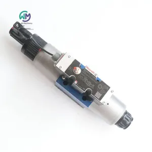
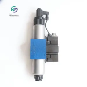
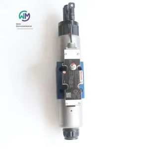
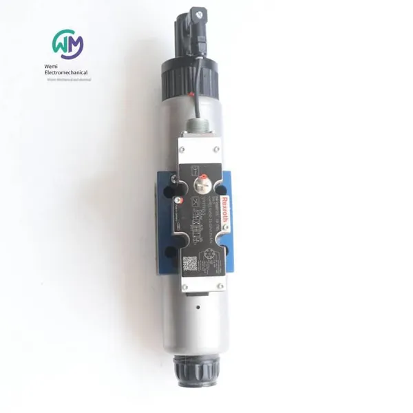
Rexroth Hydraulic Proportional Directional Valve R900927235 4wree10v50-23/g24k31/a1v


Related Products
-
 German Rexroth Electro-hydraulic Directional Control Valve 4weh16g72/6eg24n9k4US$ 553.85 - 561.54MOQ: 1 Piece
 -
Rexroth Proportional Flow Valve Amplifier Board Vt-vrpa1-151-12/v0/0US$ 738.46 - 769.23MOQ: 1 Piece
-
Rexroth Four-way Proportional Valve 4wrz25e325-73/6eg24n9ek4/d3mUS$ 2384.62 - 2461.54MOQ: 1 Piece
-
Rexroth Throttle Valve Z2fs16-8-31/sUS$ 476.92 - 492.31MOQ: 1 Piece
-
Rexroth Double One-way Throttle Valve Z2fs6-2-46/2qvUS$ 141.54 - 150.77MOQ: 1 Piece
Rexroth Hydraulic Proportional Directional Valve R900927235 4WREE10V50-23/G24K31/A1V, the main product of Shanghai Weimi Mechanical & Electrical Equipment Co., Ltd. Sales hotline: 13524123009; Contact person: Lei Qing; Product real - shot pictures, original and genuine products, in - stock inventory, affordable prices; Warmly welcome new and old customers to consult and purchase!
Rexroth Hydraulic Proportional Directional Valve 4WREE10V50-2X/G24K31/A1V
R900927235 4WREE10V50-23/G24K31/A1V
Nominal size 10, Symbol V, Electric with integrated electronic components, 24 V DC
Industrial hydraulic valves in the high - performance range; Reliably control the oil flow direction according to the hydraulic symbol; Achieve high precision through internal piston position feedback
Industrial high - performance hydraulic valves
Spool valve
Direct - acting
Connection diagram ISO 4401-05-04-0-05
Maximum pressure [bar] 315
Maximum volume flow [l/min] 180
Piston symbol Symbol V
Control Integrated electronic components
Connection type Plate - type structure
Nominal flow rate [l/min] 50
Nominal size 10
Drive type Electric with integrated electronic components
Number of connections 4
Number of switching positions 3
Power supply voltage 24 VDC
Electrical plug 7 - pin device plug (6 + PE)
Electrical connection description 7 - pin device plug (6 + PE), compliant with EN 175201-804
Connection Analog, set value ±10 V
Hydraulic oil HL,HLP,HLPD,HVLP,HVLPD,HETG,HEES,HEPG,HFDU,HFDR
Seal FKM
Weight [kg] 6.22
Rexroth Two - way Cartridge Valve, pressure control function
LFA..DB (Standard)
Specification 16 … 100
Maximum working pressure 420 bar
Specification 16 … 100
The two - way cartridge valve for pressure function is a pilot - operated seat valve or spool valve. The power unit designed as a cartridge valve is installed in the receiving hole standardized according to DIN ISO 7368 and closed with a control cover.
The pilot control valve for manual or electric proportional pressure regulation is integrated into the control cover as a pilot valve or installed on the control cover, and its installation dimensions comply with DIN 24 340.
Different pressure functions can be achieved by combining the cartridge valve with the control cover.
Pressure relief function
The cartridge valve (model LC .DB...) for the pressure relief function is designed as a seat valve without area difference (no effective area at port B). The effective pressure at port A is introduced to the spring side of the element through the pilot oil supply orifice. At the pressure set on the pilot control valve, the spool is pressure-compensated and closed by the spring force.
When the set pressure is reached, the spool opens, and the pressure at port A will be limited according to the pressure-fluid characteristics.
Pressure reduction function
Open in the rest position
The cartridge valve for the pressure reduction function is designed as a spool valve without area difference (no effective area at port B).
As the pilot control valve, the same cover type (model LFA..DB...) with pressure relief function should be used.
The effective pressure at port A is introduced to the spring side of the spool through the pilot oil supply orifice. Under the performance limit and the pressure set by the pilot control valve, the spool is pressure-compensated by the spring force and kept in the open position to achieve free flow from port B to port A.
When the set pressure is reached, the spool closes and the pressure at port A will decrease according to the pressure-fluid characteristics.
Order numbers and models of German Rexroth cartridge valve covers:
R900912751 LFA16DB2-71/050
R900938082 LFA40DB2-71/050
R900912763 LFA32DB2-71/050
R900938082 LFA40DB2-7X/050
R900938092 LFA40DBS2-7X/315
R900973333 LFA80DB2-63/100X99F35
1815500269 LFR40DBE49-10/
Rexroth two-way cartridge valve, pressure control function
LFA..DB (high pressure)
Control cover for pressure control function
The two-way cartridge valve for pressure function is a pilot-operated seat valve or spool valve. The power unit designed as a cartridge valve is installed in the receiving hole complying with ISO 7368 standard and closed with a control cover.
The pilot control valve for manual or electric proportional pressure regulation is integrated into the control cover or installed on the control cover.
By combining the cartridge valve with the control cover, different pressure functions can be achieved.
Pressure limiting function
The cartridge valve (model LC . DB...) for pressure limiting is designed as a seat valve without area difference (no effective area at port B). The effective pressure at port A is introduced to the spring side of the component through the pilot oil supply orifice. At the pressure set by the pilot control valve, the spool will compensate for the pressure by the spring force and close. When the set pressure is reached, the spool opens, and the pressure at port A will be limited according to the pressure-fluid characteristics.
Rexroth two-way cartridge valve, pressure control function
LFA..DBW
Size 16 … 100
Component series 6X, 7X
Maximum working pressure 420 bar
Size 16 … 100
Component series 6X, 7X
The two-way cartridge valve for pressure function is a pilot-operated seat valve or spool valve. The power unit designed as a cartridge valve is installed in the receiving hole standardized according to DIN ISO 7368 and closed with a control cover.
The pilot control valve for manual or electric proportional pressure adjustment is integrated into the control cover as a pilot valve or installed on the control cover, and its installation dimensions comply with DIN 24 340.
By combining the cartridge valve with the control cover, different pressure functions can be achieved.
Pressure relief function
The cartridge valve (model LC .DB...) for pressure relief function is designed as a seat valve without area difference (no effective area at port B). The effective pressure at port A is introduced to the spring side of the component through the pilot oil supply orifice. At the pressure set on the pilot control valve, the spool is pressure-compensated and closed by the spring force.
When the set pressure is reached, the spool opens, and the pressure at port A will be limited according to the pressure-fluid characteristics.
Pressure reducing function
Open in the rest position
The cartridge valve for pressure reducing function is designed as a spool valve without area difference (no effective area at port B).
As the pilot control valve, the same cover type (model LFA..DB...) with pressure relief function should be used.
The effective pressure at port A is introduced to the spring side of the spool through the pilot oil supply orifice. Under the performance limit and the pressure set by the pilot control valve, the spool is pressure-compensated by the spring force and kept in the open position to achieve free flow from port B to port A.
When the set pressure is reached, the spool closes and the pressure at port A will decrease according to the pressure-fluid characteristics.
Order numbers and models of Rexroth two-way cartridge valve control covers from Germany:
R900912764 LFA25DB2-71/420
R900912810 LFA25DBW2-7X/315
R900912816 LFA32DBW2-7X/420
Rexroth two-way cartridge valves, pressure control function
LFA..DBU2A
R900947692 LFA25DBU2A2-71/100A025
R900923101 LFA25DBU2A2-71/315A200
R900932664 LFA32DBU2B2-71/315A200
Size 16 … 100
Component series 6X, 7X
Maximum working pressure 420 bar
Size 16 … 100
Component series 6X, 7X
The two-way cartridge valves for pressure function are pilot-operated seat valves or spool valves. The power unit designed as a cartridge valve is installed in a standardized receiving bore according to DIN ISO 7368 and closed with a control cover.
The pilot control valve for manual or electric proportional pressure adjustment is integrated into the control cover as a pilot valve or installed on the control cover, and its installation dimensions comply with DIN 24 340.
Different pressure functions can be achieved by combining the cartridge valve with the control cover.
Pressure relief function
The cartridge valve for pressure relief function (model LC .DB...) is designed as a seat valve with no area difference (no effective area at port B). The effective pressure at port A is introduced to the spring side of the element through the pilot oil supply orifice. At the pressure set on the pilot control valve, the spool is pressure-compensated and closed by the spring force.
When the set pressure is reached, the spool opens, and the pressure at port A will be limited according to the pressure-fluid characteristics.
Pressure reduction function
Open in the rest position
The cartridge valve for pressure reduction function is designed as a spool valve with no area difference (no effective area at port B).
As the pilot control valve, the same cover type with pressure relief function (model LFA..DB...) should be used.
The effective pressure at port A is introduced to the spring side of the spool through the pilot oil supply orifice. Under the performance limit and the pressure set by the pilot control valve, the spool is pressure-compensated by the spring force and kept in the open position to achieve free flow from port B to port A.
When the set pressure is reached, the spool closes and the pressure at port A will decrease according to the pressure-fluid characteristics.
Rexroth Cartridge Valve Cover LFA25DBU2A2-7X/315A100
R900929835
Nominal size 25, manual pressure setting, double, switchable, with mounting surface ISO4401
Control cover for 2-way cartridge valve. According to the hydraulic symbol, it can achieve reliable pressure limitation when combined with a 2-way cartridge valve.
Hexagon
Multiple pressure levels
Pressure [bar] 420
Connection type: Plate structure
Nominal size 25
Drive type: Manual pressure adjustment
Hydraulic oil: HL, HLP, HLPD, HVLP, HVLPD, HFC
Seal: NBR
Weight [kg] 3.3
Rexroth REXROTH 2-way Actively Controllable Cartridge Valve
LC2A
Specifications: 16 … 125
Component series: 1X
Maximum working pressure: 450 bar
Maximum flow rate: 17000 l/min
Specifications: 16 … 125
Component series: 1X
2/2-way actively controllable directional cartridge valve ("two-stage active logic")
Modular design, flexible oil circuit setting
Mounting holes conforming to ISO 7368
Adopting flow-optimized geometry to ensure energy efficiency
Adopting integrated shaft seals to ensure no leakage
With spool position monitoring "closed" and/or "open" or analog (also reconfigurable)
BG certificate
The 2-way cartridge valve of type LC2A (hereinafter referred to as "active logic") adopts a compact modular design. Its basic composition includes an insert (control spool) and a socket, an intermediate cover as a fixed functional unit, and a control cover of type LFA (which is part of the Rexroth standard logic program). This control cover (ordered separately) establishes the connection with the pilot control valve and/or other hydraulic components, and integrates most of the different functions in this way - independent of the basic assembly. Almost all standard and special control covers of type LFA can be installed. Optionally, the active logic can be used for position switches. By default, the "closed" position of the control spool will be recorded. The receiving holes for the position switches are standard. This means that the position switch "Q7" can be installed at any time without adjustment. In contrast to the logic assembly which has only one control area in the spring chamber ("passive logic"), the name "active logic" obviously represents the model with a differential spool, which has at least one additional control area A4 ("two-stage active logic"). This area allows the active logic to be opened or kept open by the pilot pressure (without the pressure of the main ports A or B). The spring chamber area A5 of the control spool is composed of separate areas A1 + A2 + A4. Compared with the passive logic without the control area A4, this results in redundant areas, which can provide advantages during closing and keeping closed (redundant force, closing rate) through a suitable hydraulic oil circuit.
Active logic for directional control function
Depending on the task, the spool valve model may vary. The active area can be connected to the available pilot oil guide ring in almost any way, so that most different functions can be achieved with only one basic assembly.
Mounting holes
The LC2A active logic can be directly installed in the standard mounting holes according to ISO 7368. Therefore, it is also suitable for retrofitting existing "passive logic" where there must be no internal leakage, position monitoring is required, or a faster closing time is needed.
Rexroth REXROTH two-way directional control function cartridge valve
LFA..D (standard)
R900925453 LFA25D-71/FX08
R900924596 LFA32D-7X/FX15
R900912619 LFA16E-71/CA40DQMG24F
Standard series
Size 16 … 160
Component series 6X, 2X, 7X
Maximum working pressure 420 bar
Maximum flow rate 25000 l/min
With remote control port
The two-way cartridge valve is a component specifically designed for compact oil circuit block design. The power unit connecting A and B is installed in the receiving hole in the multi-way valve that complies with ISO 7368 standard and is closed with a cover. In most cases, this cover also serves as the connection from the control side of the power unit to the pilot control valve. By using the corresponding pilot control valve for control, the power unit can be applied to pressure, direction, and throttling functions, or a combination of these functions. A particularly effective solution is achieved by adjusting multiple flow specifications of each pipeline of the actuator. Applying the power unit of the component to multiple functions is highly cost-effective.
The two-way cartridge valve usually consists of a control cover and a mounting kit. The control cover contains control holes and an optional stroke limit function, a hydraulically controlled directional seat valve, or a shuttle valve that meets the required overall function. In addition, an electric directional spool valve or seat valve can be installed at the control cover. The mounting kit includes a bushing, a ring (only applicable to the NG32 model at most), a valve frame, optionally with or without attenuation damping, and a closing spring.
The function of the two-way cartridge valve is related to pressure. In this way, three key pressurized areas can be achieved for the function.
Two-way directional control function cartridge valve
LFA..D (high pressure)
Control cover for directional control function
The two-way cartridge valve is a component specifically designed for compact oil circuit block design. The power unit connecting A and B is installed in the receiving hole in the multi-way valve that complies with ISO 7368 standard and is closed with a cover. In most cases, this cover also serves as the connection from the control side of the power unit to the pilot control valve. By using the corresponding pilot control valve for control, the power unit can be applied to pressure, direction, and throttling functions, or a combination of these functions. A particularly effective solution is achieved by adjusting multiple flow specifications of each pipeline of the actuator. Applying the power unit of the component to multiple functions is highly cost-effective.
The general composition of a two-way cartridge valve consists of a control cover and an installation kit. The control cover contains control holes and an optional stroke limit function, a hydraulically controlled directional seat valve, or a shuttle valve that meets the required overall function. In addition, an electric directional spool valve or seat valve can be installed at the control cover. The installation kit includes a bushing, a ring (only applicable to the NG32 model at most), a valve frame, optionally with or without attenuation damping, and a closing spring.
The function of the two-way cartridge valve is related to pressure. In this way, three key pressurized areas can be achieved for the function.
Rexroth two-way directional control function cartridge valve
LFA..H2 (Standard)
Standard series
Size 16 … 160
Component series 6X, 2X, 7X
Maximum working pressure 420 bar
Maximum flow rate 25000 l/min
With remote control port
With stroke limit
The two-way cartridge valve is a component specifically designed for compact oil manifold design. The power unit connecting A and B is installed in the receiving hole that complies with the ISO 7368 standard in the multi-way valve and is closed with a cover. In most cases, this cover is also the connection from the control side of the power unit to the pilot control valve.
By using the corresponding pilot control valve for control, the power unit can be applied to pressure, direction, and throttling functions, or a combination of these functions. A particularly effective solution is achieved by adjusting multiple flow specifications of each pipeline of the actuator. Applying the power unit of the component to multiple functions is highly cost-effective.
The two-way cartridge valve usually consists of a control cover and an installation kit. The control cover contains control holes and an optional stroke limit function, a hydraulically controlled directional seat valve, or a shuttle valve that meets the required overall function. In addition, an electric directional spool valve or seat valve can be installed at the control cover. The installation kit includes a bushing, a ring (only applicable to the NG32 model at most), a valve frame, optionally with or without attenuation damping, and a closing spring.
The function of the two-way cartridge valve is related to pressure. In this way, three key pressurized areas can be achieved for the function.
Order numbers and models of German Rexroth two-way cartridge valve covers:
R900912652 LFA16H1-7X/F
R900912655 LFA16H2-7X/F
R900912694 LFA25H2-7X/F
R900912728 LFA32H2-7X/F
R900336728 LFA40H2-71/FX20
1815500315 LFR16H8-1X/FX08
Rexroth Two-way Direction Control Function Cartridge Valves
LFA..WEA
R900912683 LFA25WEA-7X/A10P10
R900955459 LFA40EWA-7X/CA20DQMG24
1815500295 LFR25WEA105-10/
1815500274 LFR32WEA105-1X/
Standard Series
Size 16 … 160
Component Series 6X, 2X, 7X
Max. Working Pressure 420 bar
Max. Flow Rate 25000 l/min
For setting direction valves
Two-way cartridge valves are components specifically designed for compact oil circuit block designs. The power unit connecting A and B is installed in the receiving hole of the multi-way valve that complies with the ISO 7368 standard and is closed with a cover. In most cases, this cover is also the connection from the control side of the power unit to the pilot control valve.
By using the corresponding pilot control valve for control, the power unit can be applied to pressure, direction, and throttling functions, or a combination of these functions. A particularly effective solution is achieved by adjusting multiple flow specifications of each pipeline of the actuator. Applying the power unit of the component to multiple functions is highly cost-effective.
Two-way cartridge valves usually consist of a control cover and an installation kit. The control cover contains control holes and an optional stroke limit function, a hydraulically controlled directional seat valve, or a shuttle valve that meets the required overall function. In addition, an electric directional slide valve or seat valve can be installed at the control cover. The installation kit includes a bushing, a ring (only applicable to the NG32 model at most), a valve frame, optionally with or without damping, and a closing spring.
The function of the two-way cartridge valve is related to pressure. In this way, three key pressurized areas can be achieved for the function.
Rexroth Two-way Direction Control Function Cartridge Valves
LFA..WEB
Standard Series
Size 16 … 125
Component Series 6X, 2X, 7X
Max. Working Pressure 420 bar
Max. Flow Rate 25000 l/min
For setting direction valves
Two-way cartridge valves are components specifically designed for compact oil circuit block designs. The power unit connecting A and B is installed in the receiving hole of the multi-way valve that complies with the ISO 7368 standard and is closed with a cover. In most cases, this cover is also the connection from the control side of the power unit to the pilot control valve.
By using the corresponding pilot control valve for control, the power unit can be applied to pressure, direction, and throttling functions, or a combination of these functions. A particularly effective solution is achieved by adjusting multiple flow specifications of each pipeline of the actuator. Applying the power unit of the component to multiple functions is highly cost-effective.
Two-way cartridge valves are usually composed of a control cover and an installation kit. The control cover contains control holes and an optional stroke limiting function, a hydraulically controlled directional seat valve, or a shuttle valve that meets the required overall function. In addition, an electric directional spool valve or seat valve can be installed at the control cover. The installation kit includes a bushing, a ring (which can only be used for the NG32 model at most), a valve frame, optionally with or without damping, and a closing spring.
The function of the two-way cartridge valve is related to pressure. In this way, three key pressurized areas can be achieved for the function.
Rexroth two-way directional control function cartridge valve
LFA..GWA
Standard series
Specification 16 … 100
Component series 6X, 7X
Maximum working pressure 420 bar
Maximum flow rate 25000 l/min
Used for setting the directional valve
With integrated shuttle valve
The two-way cartridge valve is a component specifically designed for compact oil circuit block design. The power unit connecting A and B is installed in the receiving hole that meets the ISO 7368 standard in the multi-way valve and is closed with a cover. In most cases, this cover is also the connection from the control side of the power unit to the pilot control valve.
Controlled by the corresponding pilot control valve, the power unit can be applied to pressure, direction, and throttling functions, or a combination of these functions. A particularly effective solution is achieved by adjusting multiple flow specifications of each pipeline of the actuator. Applying the power unit of the component to multiple functions is highly cost-effective.
Two-way cartridge valves are usually composed of a control cover and an installation kit. The control cover contains control holes and an optional stroke limiting function, a hydraulically controlled directional seat valve, or a shuttle valve that meets the required overall function. In addition, an electric directional spool valve or seat valve can be installed at the control cover. The installation kit includes a bushing, a ring (which can only be used for the NG32 model at most), a valve frame, optionally with or without damping, and a closing spring.
The function of the two-way cartridge valve is related to pressure. In this way, three key pressurized areas can be achieved for the function.
Order numbers and models of the cover plates of Rexroth two-way cartridge valves from Germany:
R900926535 LFA25GWA-71/P10
R900912635 LFA16GWA-71/A10P10
R900936188 LFA16GWA-71/A08P08
R900912725 LFA32KWA-7X/
R900912708 LFA32GWA-7X/
Rexroth Internal Gear Pumps
PGF
Frame sizes: 1, 2, 3
Specifications: 1.7 … 40
Component series: 2X, 3X
Maximum working pressure: 250 bar
Maximum displacement: 40.5 cm³
Features
Fixed displacement
Low operating noise
Low pulsation flow
High efficiency even at low viscosities due to sealed clearance compensation
Long service life thanks to sliding bearings and sealed clearance compensation
Suitable for a wide range of viscosities and speeds
Suction characteristics
All frame sizes and specifications can be combined with each other
Can be combined with internal gear pumps PGH, vane pumps PV7, and axial piston pumps
Valve technology can be integrated into the connection cover upon request
Drives with low to medium performance and pressure ranges in industrial applications, such as machine tools
Fatigue-resistant drives with high working pressures in mobile machinery applications, such as lifting equipment, fans, and expanders
PGF type hydraulic pumps are internal gear pumps with constant displacement and leakage clearance compensation. They basically consist of a housing, bearing cover, end cover, internal gear, pinion shaft, bearings, axial gaskets, stop pins, and segmented filling components. The segmented filling components include segments, sector supports, and sealing rollers.
Suction and discharge processes
The pinion shaft installed according to hydrodynamics drives the internal gear in the indicated rotation direction. During rotation, the volume in the suction range increases by more than about 180°. The underpressure causes the hydraulic oil to flow into the cavity. The sickle-shaped segmented filling component separates the suction part from the pressure chamber. Inside the pressure chamber, the teeth of the pinion shaft mesh again with the teeth of the internal gear. The liquid is discharged through the pressure channel.
The axial compensation force FA acts inside the pressure chamber and is generated together with the pressure field in the axial gasket. Therefore, the longitudinal liquid clearance between the rotating and fixed components is very small, ensuring the liquid sealing of the pressure chamber.
The radial compensation force FR acts on the segments and sector supports. The area ratio between the segments and sector supports and the position of the plate seal should be designed to ensure a nearly leak-free seal between the internal gear, segmented filling elements, and pinion shaft. The spring element under the plate seal ensures sufficient contact pressure even at low pressures.
Hydrodynamic and hydrostatic installation
The forces acting on the pinion shaft are borne by the radially sliding bearings lubricated hydrodynamically; the forces acting on the internal gear are borne by the hydrostatic bearings.
Gear tooth system
The gear tooth system is an involute tooth system. When the meshing length is large, the filling flow and pressure fluctuations are small; the reduction of the pulsation speed significantly reduces the operating noise.
Materials used
Housing, bearing cap, end cover and axial gasket: Aluminum alloy. Internal meshing gears, pinion shaft and stop pin: Steel. Plain bearings: Copper-tin with steel backing segments and sector support: Brass alloy. Plate seals: Plastic
Order numbers and models of German Rexroth internal meshing gear pumps:
R900932132 PGF1-2X/1,7RA01VP1
R900086159 PGF1-2X/1,7RE01VU2
R900086159 PGF1-21/1,7RE01VU2
R900952850 PGF1-21/3,2LN12VM-A387
R901021469 PGF1-21/1,7LA01VP1-A340B
R900932136 PGF1-2X/4,1RA01VP1
R900932136 PGF1-21/4,1RA01VP1
R900932183 PGF1-21/1,7LA01VP1
R900086166 PGF1-21/2,2RL01VM
R900086163 PGF1-2X/4,1RE01VU2
R900932137 PGF1-2X/5,0RA01VP1
R900932135 PGF1-2X/3,2RA01VP1
R900952850 PGF1-2X/3,2LN12VM-A387
R900932261 PGF2-2X/019RE01VE4
R900932269 PGF2-22/016RE20VU2
R900932271 PGF2-22/011RE01VE4
R900932267 PGF2-22/016RE01VE4
R900932266 PGF2-2X/008RE01VE4
R900571401 PGF2-2X/019RA20VP2
R900932274 PGF2-2X/013RE01VE4
R900931660 PGF2-2X/006RJ01VU2
R900932269 PGF2-2X/016RE20VU2
R900938281 PGF2-22/011RJ01VU2
R900930689 PGF2-22/013RJ01VU2
R900564037 PGF2-2X/008RA01VP2
R900032712 PGF2-2X/013RA20VP2
R901018829 PGF2-2X/016RJ01VU2
R900779104 PGF2-2X/011RJ01VU2K
R900983936 PGF2-2X/011RE01VE4K
R900932111 PGF3-31/040RE07VE4
R987046566 PGF3-31/025RE07VE
R900932112 PGF3-3X/032RE07VE4
R900029617 PGF3-3X/025RJ07VU2
The internal gear pumps of Bosch Rexroth (BOSCH-REXROTH) can provide the required volumetric flow rate with high efficiency over a wide speed range, thus making an important contribution to energy saving. Their low moment of inertia enables dynamic drive. Variable speed drives with internal gear pumps are a low-noise alternative to traditional variable pump systems.
Rexroth REXROTH internal gear pump PGF2-2X/016RE20VU2
R900932269
Internal gear pump, size 16, pressure 250 bar, suitable for industrial and mobile applications, open circuit
Suitable for variable speed drives, low noise and low pulsation level, high efficiency through clearance compensation, suitable for 2 million load changes under pressure
Aluminum housing
Constant displacement internal gear pump
Suitable for industrial or mobile applications with open-loop control
With FKM seals
Displacement type: constant
Nominal size [cm³] 16
Maximum pressure [bar] 250
Maximum volumetric flow [l/min] 57.6
Shaft end: cylindrical Ø 20 with sliding key, ISO 3019-2
Through drive: yes
Rotation direction: right turn
Fasteners: 2-hole mounting flange 82-2, compliant with ISO 3019-1
Hydraulic oil: HL, HLP, HEES, HEPR
Seal: FKM
Weight [kg] 4.84
Rexroth REXROTH internal gear pump
PGH-2X
Frame size: 2, 3
Size: 5 … 16
Component series: 2X
Maximum working pressure: 350 bar
Maximum displacement: 16 cm³
Features
Fixed displacement
Low operating noise
Low pulsating flow
Due to the sealing clearance compensation, efficiency can also be achieved at low speeds and low viscosities.
Suitable for a wide range of viscosities and speeds
Arbitrary combinations are possible between all frame sizes and specifications.
Can be used in combination with internal gear pumps, radial piston pumps, and external gear pumps.
The PGH type hydraulic pump is a clearance-compensated internal gear pump with a constant displacement.
They are basically composed of a housing, a bearing cover, an end cover, an internal gear, a pinion shaft, bearings, axial gaskets, an end cover, a mounting flange, a stop pin, and a segmented filling component. The segmented filling component includes: segments, sector supports, and sealing rollers.
Suction and discharge processes
The pinion shaft installed according to hydrodynamics drives the internal gear in the indicated rotation direction.
During the rotation process, the volume in the suction range increases by about 90°. The underpressure causes the hydraulic oil to flow into the cavity.
The suction port and the pressure chamber are separated by a sickle-shaped segmented filling component. In the pressure chamber, the teeth of the pinion shaft mesh again with the tooth gaps of the internal gear. The liquid is discharged through the pressure channel.
The axial compensation force FA acts inside the pressure chamber and is generated together with the pressure field in the axial gasket.
Therefore, the longitudinal clearance of the hydraulic shaft between the rotating parts and the fixed parts is very small, ensuring the complete sealing of the hydraulic shaft in the pressure chamber.
The radial compensation force FR acts on the segments and the sector supports.
Relying on the working pressure, the two segmented filling components are pressed against the cylinder head diameters of the pinion shaft and the internal gear.
The area ratio between the segments and the sector supports and the position of the sealing rollers should be designed to ensure a nearly leak-free clearance seal between the internal gear, the segmented filling component, and the pinion shaft.
The spring component under the sealing roller can ensure sufficient contact pressure even at low pressures.
Hydrodynamic and hydrostatic installation
The forces acting on the pinion shaft are borne by the radially sliding bearings lubricated hydrodynamically; the forces acting on the internal gear are borne by the hydrostatic bearings.
Gear tooth system
The gear teeth are of the involute tooth system. When the meshing length is large, the filling flow and pressure fluctuations are small; the reduction of the pulsation speed significantly reduces the operating noise.
The PGH model hydraulic pump is a clearance-compensated internal gear pump with a constant displacement. The pinion shaft installed according to hydrodynamics will drive the internal gear. The hydraulic oil is sucked in through the tooth side gaps of the pinion shaft and the internal gear opened in the suction range and sent to the pressure range. The suction area and the pressure range are separated by the radial compensation element and the gear meshing between the internal gear and the pinion shaft.
Order numbers and models of German Rexroth internal gear pumps:
R900951301 PGH2-22/006RE07VU2
R900951302 PGH2-22/008RE07VU2
Rexroth internal gear pump, fixed displacement
PGH-3X
Frame size: 4, 5
Specification: 20 … 250
Component series: 3X
Maximum working pressure: 350 bar
Maximum displacement: 250.5 cm³
Features
Fixed displacement
Low operating noise
Low pulsating flow
Due to the sealing gap compensation, high efficiency can be achieved even at low speeds and low viscosities.
Suitable for a wide range of viscosities and speeds
All frame sizes and specifications can be combined with each other.
Can be combined with axial piston pumps, internal gear pumps, and vane pumps
Suitable for operation with HFC hydraulic fluids (seal design "W")
Applications:
Suitable for high-power, high-pressure fatigue-resistant drives with a large number of load cycles, such as plastic processing machines, automatic presses, casting machines, and other applications using accumulator charging operations.
The PGH.-3X type hydraulic pump is a clearance-compensated internal gear pump with constant displacement.
Its basic components are: mounting flange, housing, through-shaft drive cover, pinion shaft, internal gear, sliding bearing, axial gasket, and stop pin, as well as radial compensation consisting of a sector body, a sector support, and a sealing roller.
Suction and discharge process
The pinion shaft installed according to hydrodynamics drives the internal gear in the indicated rotation direction.
Hydraulic oil is sucked in through the tooth gaps opened in the suction range. The hydraulic oil is transported from the suction range to the pressure range through the tooth gaps between the pinion and the internal gear.
Thus, the hydraulic oil is discharged from the closed tooth gaps and transported to the pressure port.
The suction area and the pressure range are separated by the radial compensation element and the gear meshing between the internal gear and the pinion shaft.
Axial compensation
The discharge area in the pressure range is axially sealed by the axial gasket.
Pressure fields are applied on the side of the axial gasket facing away from the discharge area. These pressure fields balance the axial gasket with the discharge area, thus achieving an ideal sealing effect with low mechanical losses.
Radial compensation
The radial compensation element includes a sector body, a sector support, and a sealing roller.
The sector body and the sector support are arranged in the pressure field so that the generated pressure can be basically borne by the stop pin.
A small pressure component presses the sector body and the sector support against the tooth tips of the pinion shaft and the internal gear, so that the pressure range can be sealed from the suction range by automatically adjusting the gap.
This is a prerequisite for maintaining high volumetric efficiency throughout the entire working time.
The clearance adjustment between the sector and the sector support can be carried out through the intermediate seal roller.
Hydrodynamic and hydrostatic installation
The pinion shaft is supported by a radially sliding bearing lubricated by hydrodynamic force.
The internal meshing gear is installed in the housing through hydrostatic force.
Gear tooth system
The gear tooth system with involute tooth edges has a long meshing length for lower flow and pressure pulsation, thus ensuring low-noise operation.
Order numbers and models of German Rexroth internal meshing gear pumps:
R901147100 PGH4-30/020RE11VU2
R901147104 PGH4-30/050RE11VU2
R901147103 PGH4-31/040RE11VU2
R901147115 PGH5-30/063RE11VU2
R901147116 PGH5-30/080RE11VU2
The internal gear pumps of Bosch Rexroth (BOSCH-REXROTH) can provide the required volumetric flow rate with high efficiency within a wide speed range, thus making an important contribution to energy saving. Its low moment of inertia enables dynamic drive. The variable speed drive with an internal gear pump is a low-noise alternative to the traditional variable pump system.
Rexroth internal gear pump PGH5-3X/080RE11VU2
R901147116
Internal gear pump; Nominal size 80, industrial application pressure 350 bar, open circuit
Optimized for variable speed drive. Low noise pollution and low pulsation level. High efficiency. No load change limitation
Cast iron housing
Constant displacement internal gear pump
For industrial applications with an open-loop control circuit
With FKM seals
Displacement type: constant
Nominal size [cm³] 80
Maximum pressure [bar] 350
Maximum volumetric flow rate [l/min] 240
Shaft end: cylindrical Ø 40 with sliding key, ISO 3019-2
With drive: yes
Rotation direction: right turn
Fasteners: 2-hole mounting flange 152-2, compliant with ISO 3019-1
Hydraulic oil: HLP, HEES, HFDU
Seal: FKM
Weight [kg] 43.82
Rexroth internal meshing gear pump
PGM-4X
Frame size: 4, 5
Specification: 25 … 125
Component series: 4X
Maximum working pressure: 210 bar
Maximum displacement: 125.3 cm³
Features
Low operating noise
Low pulsating flow
High efficiency can be achieved even under low viscosity conditions due to the sealing gap compensation.
Suitable for a wide range of viscosities and speeds
Applications:
Suitable for variable-speed transmission devices with a large number of load cycles, such as plastic processing machines
The PGM-4X model hydraulic pump is a clearance-compensated internal gear pump with a constant displacement. Its basic components are: mounting flange, housing, cover, pinion shaft, internal gear, sliding bearing, axial gasket, stop pin, and radial compensation composed of a sector, a sector support, and a sealing roller.
Suction and discharge processes
The pinion shaft installed according to hydrodynamics drives the internal gear in the indicated rotation direction. The hydraulic oil is sucked in through the tooth gaps opened in the suction range. The hydraulic oil is transported from the suction range to the pressure range through the tooth gaps between the pinion and the internal gear. Thus, the hydraulic oil is discharged from the closed tooth gaps and transported to the pressure oil port.
The suction area and the pressure range are separated by the radial compensation element and the gear meshing between the internal gear and the pinion shaft.
The discharge area in the pressure range is axially sealed by the axial gasket. A pressure field is applied on the side of the axial gasket facing away from the discharge area. These pressure fields balance the axial gasket with the discharge area, thus achieving an ideal sealing effect with low mechanical losses.
The radial compensation element includes a sector, a sector support, and a sealing roller. The sector and the sector support are arranged in the pressure field so that the generated pressure can be basically borne by the stop pin. A small pressure component presses the sector and the sector support against the tooth tips of the pinion shaft and the internal gear, so that the pressure range can be sealed from the suction range by automatically adjusting the gap. This is a prerequisite for maintaining high volumetric efficiency throughout the working time.
The gap adjustment of the sector and the sector support can be carried out through the middle sealing roller.
Hydrodynamic and hydrostatic installation
The pinion shaft is supported by a radially sliding bearing lubricated hydrodynamically. The internal gear is installed in the housing hydrostatically.
Gear tooth system
The gear tooth system with involute tooth edges has a long meshing length for lower flow and pressure pulsation, thus ensuring low-noise operation.
Materials used
Flange and cover plate: Cast iron
Housing and side gaskets: Aluminum
Shaft and internal gear: Steel
The PGM-4X model hydraulic pump is a clearance-compensated internal gear pump with a constant displacement.
Rexroth hydraulic proportional directional valve R900927235 4WREE10V50-23/G24K31/A1V

Send Inquiry to This Supplier

You May Also Like
-
Rexroth Proportional Valve 4wrpeh6c3b40l-31/m/24a1US$ 1661.54 - 1692.31MOQ: 1 Piece
-
Rexroth Directional Spool Valve 4weh16d72/6eg24n9ets2k4/b10US$ 453.85 - 461.54MOQ: 1 Piece
-
Bently Vibration Probe 330103-00-05-10-02-00US$ 430.77 - 438.46MOQ: 1 Piece
-
Rexroth Electro-hydraulic Directional Control Valve 4weh10d47/6eg24n9k4/b10d3US$ 492.31 - 507.69MOQ: 1 Piece
-
Rexroth Directional Slide Valve 4weh16d72/6eg24n9ek4/b10d3US$ 523.08 - 538.46MOQ: 1 Piece
-
Airtec Solenoid Valve Km-10-520-hnUS$ 120 - 123.08MOQ: 1 Piece
-
Rexroth Electro-hydraulic Directional Control Valve 4weh10j47/6eg24n9ets2k4US$ 584.62 - 592.31MOQ: 1 Piece
-
Rexroth Check Valve Z2s6-1-6x/can be Shipped on the Same DayUS$ 76.92 - 92.31MOQ: 1 Piece
-
Aventics Oil Injection Valve 0821300936US$ 76.92 - 80MOQ: 1 Piece
-
Rexroth Check Valve Z1s6d05-40/vUS$ 146.15 - 153.85MOQ: 1 Piece


