

Duplomatic Proportional Enlarged Version Ueik-11/51-24


Related Products
-
 Duplomatic Throttle Valve Ers4m-sb/40US$ 243.08 - 246.15MOQ: 1 Piece
 -
Rexroth Four-way Servo Valve 4ws2em10-52/75b11et315k8dvUS$ 3615.38 - 3661.54MOQ: 1 Piece
-
Italian Duplomatic Pressure Reducing Valve Z4m5-i/50US$ 223.08 - 227.69MOQ: 1 Piece
-
Rexroth Hydraulic Proportional Directional Valve R900927235 4wree10v50-23/g24k31/a1vUS$ 1600 - 1630.77MOQ: 1 Piece
-
German Rexroth Electro-hydraulic Directional Control Valve 4weh16g72/6eg24n9k4US$ 553.85 - 561.54MOQ: 1 Piece
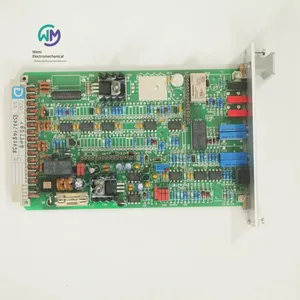
DUPLOMATIC Proportional Amplifier UEIK-11/51-24, the main product of Shanghai Weimi Mechanical & Electrical Equipment Co., Ltd. Sales hotline: 13524123009; Contact person: Lei Qing; Product real-shot pictures, genuine products from the original factory, in-stock inventory, affordable prices. We sincerely welcome new and old customers to inquire and purchase!
Italian DUPLOMATIC Electronic Control Unit
Amplifier board for open-loop single-solenoid proportional valve
UEIK-1* series
Technical parameters
Power supply 22 - 30VDC
Electrical protection for power supply Overload, Polarity reversal
Reference input signal:
Voltage 0 / +10 V
Current 4 - 20mA
Impedance of reference input signal
Voltage 10kΩ
Current 250Ω
Card size Eurocard format 100x160x35
Plug interface DIN 41612-D 32 external thread
Operating temperature range 0 - 50℃
Weight 0.2kg
The UEIK-1* type card is an Eurocard-format electronic control unit for open-loop single-solenoid proportional valves. This unit provides a variable current proportional to the reference input signal, which is not affected by temperature changes or load impedance.
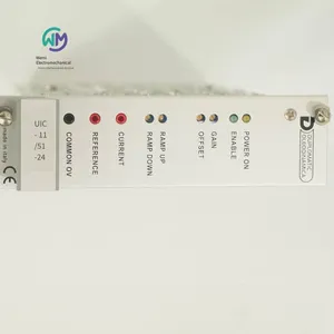
The PWM characteristic of the solenoid power supply reduces the valve's hysteresis, thereby optimizing the control accuracy. The front panel is equipped with LED lights, which can display the card's functions and potentiometers, thus optimizing the control.
Function description
Power supply
The power supply required for the card is between 22 and 30 V DC (pins 2a/2c - 4a/4c), and the required power is: 20W (UEIK-11) - 29W (UEIK-12).
The power supply voltage must be rectified and filtered, and the maximum allowable fluctuation is within the above voltage range.
Electrical protection
The card has the function of preventing overvoltage and polarity reversal.
A 2A fast-blow fuse is installed for power circuit protection.
Reference input signal
This card can accept a voltage reference input signal (0 to +10V) or a current reference input signal (4 - 20 mA).
Note: If the signal is emitted by a potentiometer, please verify that its load is at least 200 Ω.
Signals and Regulation
Power POWER ON
The yellow LED indicates the power status of the card:
On - Power is normal
Off - No power, power failure, or blown fuse
Enable ENABLE
The card requires an enabling signal of 22 to 30 V DC applied at pin 24c to work properly.
The enabling status of the card can be observed through the LED on the front panel or measured by the user at pins 6a and 6c.
The green LED indicates:
On - The card is enabled
Off - The card is disabled or faulty
Gain GAIN (Gain coefficient adjustment)
The gain potentiometer "GAIN" can adjust the relationship between the set reference signal value and the large current supplied to the electromagnet, thus limiting the maximum hydraulic size for valve control.
The maximum current of the card is limited to 1.0A (UEIK - 11) - 1.2A (UEIK - 12). See the default values in Section 6.
Rotate clockwise to increase the current.
Offset OFFSET (Offset current adjustment)
The offset potentiometer "OFFSET" can adjust the offset current of the valve. This parameter is used to eliminate the dead zone of the valve.
The adjustment range is from 0 to 0.5A (UEIK - 11) - from 0 to 0.65A (UEIK - 12).
The offset current is activated when the reference input signal exceeds the threshold of + 150 mV (or 4.25 mA).
Below this threshold, the offset is not activated, which only occurs when the polarization current is equal to 25 mA.
Note: A change in the offset current setting value will cause a corresponding change in the gain coefficient value.
Rotate clockwise to increase the current.
Ramp Up / Ramp Down (Ramp adjustment)
The ramp up potentiometer "RAMP UP" and the ramp down potentiometer "RAMP DOWN" can adjust the time required to reach the desired supply current when the corresponding reference input signal steps up or down, ranging from 0.03 to 7 seconds.
In this way, the response time of the valve can be controlled to meet the requirements of the hydraulic circuit and machine cycle.
The ramp can be disabled by applying a 22 to 30 V DC cut - off command at pin 16a. In this case, the remaining ramp time is 10 ms.
Rotate clockwise to increase the ramp time.
Signal measurement
Current CURRENT (Electromagnet current measurement point)
The current supplied to the electromagnet can be read through the voltage.
Reading conversion:
1V DC = 1A (UEIK-11)
0.82V DC = 1A (UEIK-12).
Reference signal REFERENCE (Measurement point of reference input signal)
The reference input signal sent to the card can be read through voltage.
Read directly, but the signs between the reference voltage and current are opposite, and the conversion is as follows:
4 mA = 0 V 20 mA = - 10V.
Installation
The card can be installed in a bracket or card rack, and its interface form is DIN 41612 - Specification D - 32 pins.
For power supply and electromagnet connections, it is recommended to use wires with a cross-sectional area between 1 and 2.5 mm2 according to the length. For other connections, it is recommended to use cables with a shielded sheath, and only the card side should be grounded.
Generally, the wiring of valves and electronic units must be kept as far away as possible from interference sources (such as power cables, motors, exchangers, and electrical switches).
In an environment with electromagnetic interference, the wiring must be fully protected.
Default state
The electronic unit is set at the factory when delivered.
The standard settings are as follows:
“GAIN” gain adjustment: When the reference input signal is +10V (or 20 mA), the corresponding electromagnet input current is 0.7 A.
– “OFFSET” offset adjustment: Zero
– “RAMP UP” rising ramp and “RAMP DOWN” falling ramp adjustment: Small value
– SW1 is in position V
– SW2 is in position S
– SW3 is in position AA
– Switching frequency (PWM) =
200Hz (UEIK-11)
100Hz (UEIK-12).
Commissioning and control settings
If necessary, the settings can be modified as follows:
a) Offset current adjustment
– Set the gain potentiometer “GAIN” to the minimum value.
– Input the maximum reference input signal value (+10V or 20 mA).
– Set the offset potentiometer “OFFSET” so that the valve is positioned in the starting working area.
b) Gain coefficient adjustment
– Input the maximum reference input signal value (+10V or 20 mA)
– Set the gain potentiometer “GAIN” so that the controlled hydraulic parameters reach the required maximum value.
c) Ramp adjustment
– Adjust the rising ramp potentiometer “RAMP UP” and the falling ramp potentiometer “RAMP DOWN” so that the valve opens gradually when the reference input signal changes.
Circuit settings of the card
Each operation of modifying the switch settings must be carried out when the card is powered off. Each independent switch in each module must be set to the same position.
Selection of voltage or current reference input signal
(The SW 1 module consists of three independent switches)
– Selection of voltage reference input signal V
– Selection of current reference input signal I
Selection of single-ended reference input signal or differential reference input signal
(The SW 2 module includes an independent switch)
– Selection of single-ended reference input signal S. This state is mandatory when the external potentiometer generating the reference input signal is powered by the card itself.
– Selection of differential reference input signal D. This state is preferred when the reference input signal comes from the analog output of the PLC or CNC.
Note: The SW 3 module, consisting of two independent switches, must always be set to the AA state under the standard default state.
Switching frequency adjustment
The switching frequency (PWM) can be modified by the adjuster PT7 (see Section 10).
The setting range is from 80 to 370 Hz.
Appropriate adjustment of the switching frequency can reduce the hysteresis value of the valve.
Rotate clockwise to increase the frequency.
Italian DUPLOMATIC proportional valve amplifier board
UEIK-11/51-24
UEIK-12/51-24
Italian DUPLOMATIC flange-type return oil filter FRT
Installed on the oil tank
Serial number 10
High working pressure 3 bar
The FRT-type filter is a flange-type filter installed on the oil tank cover; the oil inlet is located at the end of the filter, with BSP thread, which is easy to install.
The filter observation cover plate is fixed by three or four screws, which is easy to maintain. The filter element is also fixed by screws and can be easily removed together with the filter cartridge. In this way, we can clean the impurities in the filter housing by replacing the filter element.
The filter element is made of high-efficiency filter material and can accommodate a large amount of oil pollutants. Three different filtration accuracies are available:
F10 = 10 µm (β10 > 100) - ISO 4406:1999 grade 18/16/13
F25 = 25 µm (β25 > 100) - ISO 4406:1999 grade 19/17/14
P10 = 10 µm rated (β10 > 2) - ISO 4406:1999 grade 21/19/16
The FRT-type filter generally comes with a bypass valve.
All FST filters can be installed with electronic or visual blockage indicators, which need to be ordered separately.
Filter model: FRT-TB200
Oil port size: 2” BSP
Weight: 4.1kg
Flow rate (indicated): 430l/min
Maximum working pressure: 3bar
Filter element rupture differential pressure: 3bar
Bypass valve opening differential pressure: 1.7(±10 %) bar
Ambient temperature range: -25 / +50°C
Oil temperature range: -25 / +110°C
Oil viscosity range: 10 - 400cSt
When selecting the filter specification, it is necessary to ensure that the differential pressure of the filter is less than 0.5bar under the nominal flow rate condition. The total differential pressure through the filter is the sum of the differential pressure of the oil passing through the filter housing and the differential pressure passing through the filter element.
Filter model: FRTE - 200
Ordering model of filter element for Italian DUPLOMATIC filters:
FRTE200F25S/10N
DUPLOMATIC plunger type pressure relays, PS series
Maximum working pressure: 650 bar
Maximum pressure adjustment range: 35 - 140 - 350 - 630 bar
The PS* plunger type pressure relay is an electro - hydraulic pressure switch. When the working pressure reaches the set value, its internal electrical contacts close.
The pipeline pressure acts on the plunger, and the other end of the plunger directly bears the load from the spring. The spring force can be adjusted and set by the adjustment knob. When the pipeline pressure reaches the set value, the plunger moves and closes the micro - switch.
This pressure relay can provide 4 pressure adjustment options. The installation methods include panel mounting or 1/4” BSP threaded port connection.
The standard order includes an adjustment knob and a pressure scale.
Hydraulic oil
When using mineral hydraulic oil HL or HM that meets the ISO 6743 - 4 standard, use NBR seals (code N).
For HFDR oil (phosphate ester), use FPM seals (code V).
If using other oils, such as HFA, HFB, HFC, please consult our technical department.
When the working oil temperature is higher than 80 °C, it will cause the hydraulic oil and seals to age and deteriorate too quickly.
Please pay attention to maintaining the stable physical and chemical properties of the hydraulic oil.
Installation
Under the condition that it does not affect its normal operation, this pressure relay can be installed in any direction. Ensure that there is no air in the hydraulic circuit during use.
The PSP plate-mounted pressure relay can be fastened to the mounting plane with bolts. It is required that the flatness and roughness of the mounting plane are not lower than the levels marked in the figure. If the minimum value is not reached, leakage is likely to occur between the relay and the mounting surface.
Stack-mounted base plate
The PSP pressure relay can be stack-mounted on the mounting base plates that comply with the ISO 4401-03 (CETOP 03) standard, with the codes 1950611 and 1950621.
The mounting base plate with the code 1950611 can realize the connection between the pressure relay and the oil ports A and/or B, depending on the mounting position of the screws. The mounting base plate with the code 1950621 can connect the pressure relay to the P port.
Ordering models of Italian DUPLOMATIC pressure switches:
PSP2/21N-K1/K
PSP4/21N-K1/K
PSP6/21N-K1/K
PSP8/21N-K1/K
PST2/21N-K1/K
PST4/21N-K1/K
PST6/21N-K1/K
PST8/21N-K1/K
Italian DUPLOMATIC direct-acting pressure control valve CR
Serial number 22
Cartridge type
Maximum working pressure 350 bar
Maximum flow rate 50 l/min
The CR valve is a cartridge-type direct-acting pressure control valve, which can be installed on the manifold block or valve plate that conforms to the D-10B valve seat hole.
This valve is usually used to control the maximum pressure of the hydraulic circuit, and can also be used to limit the peak pressure generated during the movement change of the hydraulic cylinder (motor).
This valve has 5 different pressure adjustment ranges, with a maximum pressure of 350 bar.
The circuit pressure acting on the valve is balanced with the spring force. When the set pressure is reached, the valve opens, and the excess oil returns directly to the oil tank through the T port.
The pressure can be set by adjusting the screw. Usually, a countersunk hexagon socket screw is used, and a lock nut and a maximum adjustment limiter are also installed.
Maximum working pressure 350bar
Maximum flow rate 50l/min
Ambient temperature range -20 / +50°C
Oil temperature range -20 / +80°C
Oil viscosity range 10 ÷ 400cSt
Maximum allowable pollution level of the oil According to ISO 4406:1999, level 20/18/15
Recommended oil viscosity 25cSt
Weight 0,16kg
Surface galvanized treatment Fe // Zn 8 // B EN 12329
Hydraulic oil
When using mineral hydraulic oil HL or HM complying with ISO 6743-4 standard, use NBR seals (code N). For HFDR oil (phosphate ester), use FPM seals (code V). If using other oils, such as HFA, HFB, HFC, please consult our technical department. When the working oil temperature is higher than 80 °C, it will cause the hydraulic oil and seals to age and deteriorate too quickly. Please pay attention to maintaining the stable physical and chemical properties of the hydraulic oil.
Italian DUPLOMATIC cartridge relief valve
CR3/22N
CR5/22N
CR6/22N
CR4/22N
DUPLOMATIC pilot pressure control valve CRQ
Cartridge type
High working pressure 350 bar
Large flow rate 100 l/min
Working principle
- The CRQ valve is a cartridge pilot pressure control valve, which can be installed on an integrated block or valve block conforming to the D-10C valve seat hole.
- This valve is usually used to control the pressure of the hydraulic circuit. When the pressure is close to the set value, it can still enable the pump to work at full flow.
- Four different pressure adjustment ranges are available, with a maximum pressure of 350 bar. - The valve includes a balanced main spool and a pilot valve. The main spool is usually in a closed state. When the circuit pressure exceeds the value set by the pilot valve, the main spool opens, and the oil returns directly to the oil tank through the T port.
- The pressure can be set by adjusting the screw. Usually, a countersunk hexagon socket screw is used, and a lock nut and a large adjustment limiter are installed.
Technical parameters (measured at an oil temperature of 50°C and an oil viscosity of 36 cSt)
Maximum working pressure 350 bar
Maximum flow rate 100 l/min
Ambient temperature range -20 / +50°C
Oil temperature range -20 / +80°C
Oil viscosity range 10 ÷ 400 cSt
Maximum allowable pollution level of the oil According to ISO 4406:1999, grade 20/18/15
Recommended oil viscosity 25 cSt
Weight 0.16 kg
Surface galvanized treatment Fe // Zn 8 // B EN 12329
Hydraulic oil
When using mineral hydraulic oil HL or HM complying with ISO 6743-4 standard, use NBR seals. For HFDR oil (phosphate ester), use FPM seals (code V). When the working oil temperature is higher than 80 °C, it will cause the hydraulic oil and seals to age and deteriorate too quickly.
Ordering model of Italian DUPLOMATIC cartridge relief valve:
CRQ3/12
CRQ4/12
CRQ5/12
CRQ6/12
Italian DUPLOMATIC mounting plate with relief valve RM4*-MP series
Threaded oil port
High working pressure 350 bar
Large flow rate 100 l/min
- The RM4*-MP series mounting plate is equipped with a relief valve, and the T port is a threaded oil port.
- This mounting plate is used as the mounting surface for mounting plates P2D and P4D on the power unit.
- Four pressure adjustment ranges are available, up to 350 bar. - Usually supplied with a countersunk hexagon socket adjusting screw, lock nut and large adjustment limiting device.
Hydraulic oil
When using mineral hydraulic oil HL or HM in accordance with ISO 6743-4 standard, use NBR seals. For HFDR oil (phosphate ester), use FPM seals (code V). When the working oil temperature is higher than 80 °C, it will cause the hydraulic oil and seals to age and deteriorate too quickly.
Ordering model of Italian DUPLOMATIC plate relief valve:
RM4-210-MP/40N
Italian DUPLOMATIC relief valve RQ*-P
Serial number 41
Plate installation
RQ3-P ISO 6264-06 (CETOP R06)
RQ5-P ISO 6264-08 (CETOP R08)
RQ7-P ISO 6264-10 (CETOP R10)
This valve is a pilot-operated relief valve, and the main valve uses a cylindrical spool and cone seal.
The plate installation conforms to the ISO 6264 (CETOP RP 121H) standard.
The X port can be used as a remote pilot port (see the hydraulic symbol table).
The RQ*-P type valve allows the full flow of the pump to pass through when the system pressure is close to the set value of the relief valve.
The wide oil passage can reduce the pressure drop and improve energy efficiency.
RQ3-P series
Maximum working pressure 350bar
Maximum flow rate 200l/min
Ambient temperature range -20 / +50°C
Oil temperature range -20 / +80°C
Oil viscosity range 10 ÷ 400cSt
The maximum allowable pollution level of the oil is Grade 20/18/15 according to ISO 4406:1999
Recommended oil viscosity: 25cSt
Weight: 3.5kg
RQ5-P series
Maximum working pressure: 350bar
Maximum flow rate: 400l/min
Ambient temperature range: -20 / +50°C
Oil temperature range: -20 / +80°C
Oil viscosity range: 10 ÷ 400cSt
Maximum allowable oil pollution level: According to ISO 4406:1999, grade 20/18/15
Recommended oil viscosity: 25cSt
Weight: 4.3kg
RQ7-P
Maximum working pressure: 350bar
Maximum flow rate: 500l/min
Ambient temperature range: -20 / +50°C
Oil temperature range: -20 / +80°C
Oil viscosity range: 10 ÷ 400cSt
Maximum allowable oil pollution level: According to ISO 4406:1999, grade 20/18/15
Recommended oil viscosity: 25cSt
Weight: 6.5kg
Hydraulic oil
When using mineral hydraulic oil HL or HM that meets the ISO 6743-4 standard, use NBR seals. For HFDR oil (phosphate ester), use FPM seals (code V). When the working oil temperature is higher than 80 °C, it will cause the hydraulic oil and seals to age and deteriorate too quickly.
Adjustment knob
The RQ type valve can be optionally equipped with a SICBLOC adjustment knob. When operating, press the knob and rotate it. If necessary, add option M to the order model.
Order models of Italian DUPLOMATIC relief valves:
RQ3-P5/41
RQ3-P5/M/41
RQ3-P6/41
RQ5-P5/41
RQ5-W5/41
RQ5-P6/41
RQ7-P5/41
RQ7-P6/41
Italian DUPLOMATIC pilot-operated relief valve MRQ series
Stacked ISO 4401-03 (CETOP 03)
Maximum working pressure: 350 bar
Maximum flow rate: 75 l/min
The MRQ stacked valve is a pilot-operated relief valve, and its mounting surface size meets the ISO4401 (CETOP RP 121H) standard.
This valve can be combined with other valves whose mounting surface dimensions comply with the ISO 4401-03 (CETOP 03) standard to form a stack valve group through screws or bolts, without the need for oil pipe connections.
Depending on the model, this valve can adjust the pressure of a single circuit individually or adjust the pressures of two circuits simultaneously. It can provide 4 different pressure adjustment ranges.
This valve is usually used as a pressure limiting element in hydraulic circuits.
It is usually supplied with a hexagonal adjusting screw, a lock nut, and a large adjustment limiting device.
Hydraulic functions
- "SP": Control the pressure of pipeline P, and port T is for oil drainage.
- "SAT": Control the pressure of pipeline A, and port T is for oil drainage.
- "SBT": Control the pressure of pipeline B, and port T is the oil discharge port.
- "DT": Control the pressures of pipelines A and B, and port T is for oil drainage.
- "D": Control the pressures of pipelines A and B, and they serve as oil drainage ports for each other.
- "SB": Control the pressure of pipeline B, and port A is for oil drainage.
Technical parameters (measured at an oil temperature of 50°C and an oil viscosity of 36 cSt)
Maximum working pressure 350bar
Maximum flow rate of the control pipeline and the free pipeline 75l/min
Ambient temperature range -20...50°C
Oil temperature range -20...80°C
Oil viscosity range 10 ÷ 400cSt
Maximum allowable pollution level of the oil According to ISO 4406:1999, grade 20/18/15
Recommended oil viscosity 25cSt
Weight:
MRQ-SP / MRQ-SAT / MRQ-SBT / MRQ-SB 1.4kg
MRQ-DT / MRQ-D 2.1kg
Hydraulic oil
When using mineral hydraulic oil HL or HM that complies with the ISO 6743-4 standard, use NBR seals. For HFDR oil (phosphate ester), use FPM seals (code V). If using other oils, such as HFA, HFB, HFC, etc., please consult our technical department. When the working oil temperature is higher than 80 °C, it will cause the hydraulic oil and seals to age and deteriorate rapidly.
Please note to maintain the stable physical and chemical properties of the hydraulic oil.
Ordering models of Italian DUPLOMATIC relief valves:
MRQ4-SP/51
MRQ5-SP/51
MRQ6-SP/51
The DUPLOMATIC electromagnetic relief valves have unloading and pressure selection functions. RQM*-P series
Plate installation
RQM3-P ISO 6264-06 (CETOP R06)
RQM5-P ISO 6264-08 (CETOP R08)
RQM7-P ISO 6264-10 (CETOP R10)
-The RQM*-P type valve is a relief valve, which can provide three flow specifications, with a maximum flow rate of up to 500 l/min.
-The mounting base plate complies with the ISO 6264 (CETOP RP 121H) standard.
-According to different solenoid valve models selected, it can be divided into 5 types, including full-flow unloading and 3 pressure value selection functions.
-The adjustment of the secondary and tertiary pressure values can be set through the relief valve between the main valve and the solenoid valve.
-It is usually supplied with a hexagonal adjusting screw. If needed, it can also be equipped with a SICBLOC adjusting knob to adjust the main pressure control.
Technical parameters (measured under the conditions of an oil temperature of 50°C and an oil viscosity of 36cSt)
Type RQM3-P RQM5-P RQM7-P
Maximum working pressure 350bar
Maximum flow rate 200l/min 400l/min 500l/min
Ambient temperature range -20 / +50°C
Oil temperature range -20 / +80°C
Oil viscosity range 10 ÷ 400cSt
The maximum allowable pollution level of the oil According to ISO 4406:1999, grade 20/18/15
Recommended oil viscosity 25cSt
Hydraulic oil
When using mineral hydraulic oil HL or HM that complies with the ISO 6743-4 standard, use NBR seals (code N). For HFDR oil (phosphate ester), use FPM seals (code V). When the working oil temperature is higher than 80 °C, it will cause the hydraulic oil and seals to age and deteriorate too quickly. Please pay attention to maintaining the stable physical and chemical properties of the hydraulic oil.
Adjusting knob
The RQ type valve can be optionally equipped with a SICBLOC adjusting knob, but it can only be used for the main valve pressure adjustment. When operating, press and rotate.
If needed, add option M to the order model.
Electrical plug
The solenoid valve is not supplied with an electrical plug and must be ordered separately.
Manual emergency operation, with protective cover: CM
The installed solenoid valves are all exposed to the atmosphere or may be in a hot environment. It is recommended to choose a solenoid valve with a protective cover for manual emergency operation. Add option CM to the order model.
Ordering models of Italian DUPLOMATIC electromagnetic relief valves:
RQM3-P5/A/60N-D24K1
RQM3-P6/A/60N-D24K1
RQM5-P5/A/60N-D24K1
RQM3-P6/A/60N-A230K1
Italian DUPLOMATIC external gear pumps, GP series
The GP-type fixed-displacement external gear pump is equipped with axial clearance compensation.
Even under high working pressure conditions, this pump can still provide a large flow rate; it operates with low noise; and thanks to the load balancing system on the guide bushings, this pump has excellent durability.
This pump is divided into three groups of specifications, with displacements up to 9,1, 27,9, and 87,6 cm3/rev respectively. Meanwhile, its working pressure can reach up to 250 bar (standard) and 310 bar (high-pressure type H).
This pump is available in three forms: clockwise rotation, counterclockwise rotation, and reversible rotation, with a tapered shaft (standard). Other forms of shafts can be provided upon request.
This pump can be supplied in the form of a multiple pump, and various flow rates can be achieved through combination. The spline-connected power system ensures high power performance.
Installation
When installing the GP-type gear pump, its shaft can face any direction.
Before the pump starts working, it must be ensured that the rotation direction of the pump is consistent with the direction indicated by the arrow on the pump body.
Before operation, the pump casing must be filled with oil.
Before the first operation, the pump must be vented from its working oil port.
When the pump starts, especially under low-temperature conditions, it must be in an unloaded state.
Select a reasonable diameter for the oil suction pipeline to ensure smooth oil flow. Bends, throttling, or overly long pipelines will impede the normal operation of the pump. It is recommended that the flow velocity in the oil suction pipeline does not exceed 1 - 2 m/sec.
The minimum allowable relative oil suction pressure is -0,3 bar. The pump will not operate normally when the oil suction pressure is abnormal.
The working speed of the gear pump must not be lower than the minimum speed. The same working hydraulic oil must be injected before installation. Inject oil through the connecting pipeline. If necessary, the pump can be manually driven to rotate.
The connection of the motor-pump unit must be completed directly through an elastic coupling that can compensate for deviations. The coupling is not allowed to generate axial or radial loads on the pump shaft end.
Multiple pumps
Combination of multiple pumps is allowed, which means that various flow rate combinations can be achieved in independent hydraulic circuits.
When combining multiple pumps, the following requirements must be met:
When combining multiple pumps, each pump must be of the same specification or in a decreasing order of specifications.
The maximum speed of the multiple pumps is determined by the pump with the lowest speed.
The maximum allowable torque value must not be exceeded.
Ordering models of Italian DUPLOMATIC gear pumps:
GP3F0427R01F20N+GP1R0041RF20N
GP2-0095R00F/20N
GP2-0140L95B/20N
GP2-0140R97F/20N
GP2-0140R95F/20N
GP2-0095D00F/20N
GP30394R95F20N
GP3-0394R97F/20N
GP3-0427R95F/20N
GP2-0095R05B/20V
GP2-0158R97F/20N
GP2-0279R97F/20N
1P-4.2R/11N
GP1R0020RF20N
GP3F0394R97F20N+GP1R0061RF20N
GP10027R95B20NH
GP20113R97F20N
GP20140R95B20N
GP30264R97F20N
GP30337R97F20N
GP30264R97F20N
GP30337R97F20N
GP3F0394R97F20N+GP1M0061RF20N+GP1R0041RF20N
DUPLOMATIC internal gear pumps IGP
- The IGP internal gear pumps are divided into five specifications, and each specification includes a series of different displacements.
- Due to the radial and axial compensation proportional to the working pressure and low working noise, the IGP pumps have excellent performance.
- The optimized load distribution and special wear-resistant bearings enable the pumps to work continuously under high pressure and extend the working life of the pumps.
- The IGP pumps can also be supplied in the form of multiple pumps, and various flow rates can be achieved through combination.
Technical parameters
IGP pump specifications: 3; 4; 5; 6; 7
Displacement range: 3,6 - 10,2cm3/rev; 13,3 - 32,6cm3/rev,7; 33,1 - 64,9cm3/rev; 64,1 - 126,2cm3/rev; 125,8 - 251,7cm3/rev;
Flow range (at 1500 rpm): 5,4 - 15,3l/min; 19,9 - 48,9l/min; 49,6 - 97,3l/min; 96,1 - 189,3l/min; 188,7 - 377,5l/min;
Rotation direction: Clockwise or counterclockwise (viewed from the shaft end)
Hydraulic connection: Flange joint SAE J518 c
Installation form: Flange SAE J744 c
Weight (single pump): 4-4.8kg; 8.6-11kg; 15.5-18.7kg; 29.2-35kg; 46.5-59kg;
Ambient temperature range: -10/+60℃
Oil temperature range: -10/+80℃
Recommended oil viscosity: 25-100cSt
Hydraulic oil type
Use mineral-based hydraulic oil with anti-foaming agent and antioxidant.
Hydraulic oil viscosity:
The working viscosity of hydraulic oil must be within the following range:
Minimum viscosity 10 cSt at the maximum working temperature of 80 °C for the oil
Optimal viscosity 25 - 100 cSt at the working temperature of the oil in the tank
Maximum viscosity 2000 cSt during the pump startup phase
When selecting the oil, it is necessary to ensure that the actual viscosity of the hydraulic oil is within the above range at the working temperature.
Ordering model of the internal gear pump of Italian DUPLOMATIC:
IGP3-006-R05/11N
DUPLOMATIC proportional amplifier UEIK-11/51-24

Send Inquiry to This Supplier

You May Also Like
-
Rexroth Proportional Flow Valve Amplifier Board Vt-vrpa1-151-12/v0/0US$ 738.46 - 769.23MOQ: 1 Piece
-
Rexroth Four-way Proportional Valve 4wrz25e325-73/6eg24n9ek4/d3mUS$ 2384.62 - 2461.54MOQ: 1 Piece
-
Rexroth Throttle Valve Z2fs16-8-31/sUS$ 476.92 - 492.31MOQ: 1 Piece
-
Rexroth Double One-way Throttle Valve Z2fs6-2-46/2qvUS$ 141.54 - 150.77MOQ: 1 Piece
-
Rexroth Proportional Valve 4wrpeh6c3b40l-31/m/24a1US$ 1661.54 - 1692.31MOQ: 1 Piece
-
Rexroth Directional Spool Valve 4weh16d72/6eg24n9ets2k4/b10US$ 453.85 - 461.54MOQ: 1 Piece
-
Bently Vibration Probe 330103-00-05-10-02-00US$ 430.77 - 438.46MOQ: 1 Piece
-
Rexroth Electro-hydraulic Directional Control Valve 4weh10d47/6eg24n9k4/b10d3US$ 492.31 - 507.69MOQ: 1 Piece
-
Rexroth Directional Slide Valve 4weh16d72/6eg24n9ek4/b10d3US$ 523.08 - 538.46MOQ: 1 Piece
-
Airtec Solenoid Valve Km-10-520-hnUS$ 120 - 123.08MOQ: 1 Piece