

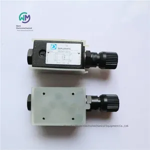
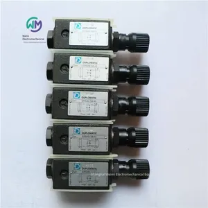
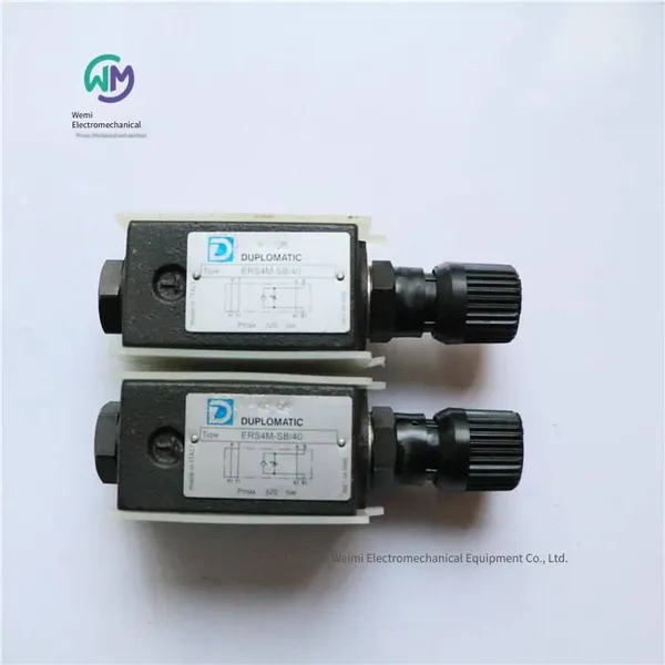
Duplomatic Throttle Valve Ers4m-sb/40


Related Products
-
 Rexroth Four-way Servo Valve 4ws2em10-52/75b11et315k8dvUS$ 3615.38 - 3661.54MOQ: 1 Piece
 -
Italian Duplomatic Pressure Reducing Valve Z4m5-i/50US$ 223.08 - 227.69MOQ: 1 Piece
-
Rexroth Hydraulic Proportional Directional Valve R900927235 4wree10v50-23/g24k31/a1vUS$ 1600 - 1630.77MOQ: 1 Piece
-
German Rexroth Electro-hydraulic Directional Control Valve 4weh16g72/6eg24n9k4US$ 553.85 - 561.54MOQ: 1 Piece
-
Rexroth Proportional Flow Valve Amplifier Board Vt-vrpa1-151-12/v0/0US$ 738.46 - 769.23MOQ: 1 Piece
DUPLOMATIC Throttle Valve ERS4M-SB/40, the main product of Shanghai Weimi Mechanical & Electrical Equipment Co., Ltd. Sales hotline: 13524123009; Contact person: Lei Qing; Product real-shot pictures, original genuine products from the factory, in-stock inventory, affordable prices; We sincerely welcome new and old customers to consult and purchase!
Italian DUPLOMATIC Throttle Valve ERS4M
Stackable type
CETOP 05
p max 320 bar
Working principle
- This valve is a flow control valve without compensation. The valve is equipped with a built-in check valve, allowing free reverse flow of the fluid. This valve is of the stackable type, and its installation dimensions comply with CETOP and ISO standards.
- Without the need for oil pipes, this valve can be quickly assembled with other CETOP 05 valves into a stack valve group by bolts or screws.
- Usually, it is supplied with a SICBLOC knob. This knob has a scale indication and can be self-locked. Press and rotate it during operation.
Hydraulic functions:
- Function "SA": Used when it is necessary to control the flow rate flowing from the actuator into pipeline A.
- Function "SB": Used when it is necessary to control the flow rate flowing from the actuator into pipeline B.
- Function "D": Control the discharge oil volume from the two chambers of the actuator respectively.
- Function "RD": Control the input flow rate into the two chambers of the actuator respectively.
- All models of this valve are equipped with a built-in check valve, allowing free reverse flow. (Opening pressure 0.5 bar).
Technical parameters (measured at an oil temperature of 50℃ and an oil viscosity of 36cST)
Maximum working pressure 320bar
Check valve opening pressure 0.5bar
Maximum flow rate of the control pipeline 80l/min
Maximum flow rate of the free pipeline 100l/min
Ambient temperature range –20 ~ +50℃
Oil temperature range –20 ~ +70℃
Oil viscosity range 2,8 ~ 380cSt
Recommended filtration accuracy ≤ 25µm
Recommended oil viscosity 25cSt
Weight 3.1kg
Hydraulic oil
Normally, mineral oil with anti-foaming agents and anti-oxidants should be used.
Ordering model of Italian DUPLOMATIC Throttle Valve:
ERS4M-SB/40
Italian DUPLOMATIC Pilot-operated Check Valve MVPP
Stacked type
ISO 4401-03
High working pressure 350 bar
The MVPP valve is a stacked-type hydraulically controlled check valve (closed by a spring and sealed by a poppet valve core). Its mounting surface dimensions comply with the ISO 4401 standard.
The main functions of this valve:
Prevent the flow of oil in one direction;
If the pilot pressure opens the valve, allow the oil to flow in the above direction;
Allow the oil to flow freely in the other direction.
The MVPP valve is usually installed under the electromagnetic directional valve complying with the ISO 4401-03 (CETOP 03) standard. It can also be combined with other valves complying with the ISO 4401-03 standard to form a stacked valve group.
Structure
Structure "SA" - "SB": Used for one-way locking of the actuator position.
Structure "D": Used for two-way locking of the actuator position.
Technical parameters (measured at an oil temperature of 50°C and an oil viscosity of 36 cSt)
Maximum working pressure 350bar
Check valve opening pressure 3bar
Maximum flow rate of the control pipeline 50l/min
Maximum flow rate of the free-flow pipeline 75l/min
Pressure ratio between the sealed cavity and the pilot port 3,4:1
Ambient temperature range -20 / +50 °C
Oil temperature range -20 / +80 °C
Oil viscosity range 10 ÷ 400 cSt
Maximum allowable pollution level of the oil According to ISO 4406:1999 grade 20/18/15
Recommended oil viscosity 25 cSt
Mass: 1.3kg
Hydraulic oil
When using mineral hydraulic oil HL or HM complying with the ISO 6743-4 standard, use NBR seals. For HFDR oil (phosphate ester), use FPM seals (code V).
DUPLOMATIC Check Valve Ordering Model:
MVPP-D/50
MVPP-SA/50
MVPP-SB/50
Italian DUPLOMATIC Direct-acting Check Valve MVR
Stacked ISO 4401-03
High working pressure 350 bar
The MVR type stack valve is a direct-acting check valve, and its mounting surface size complies with the ISO 4401 standard.
This valve is mainly used to prevent oil backflow in the circuit and for automatic unloading. It can also be used to generate back pressure.
This valve can be combined with other valves complying with the ISO 4401-03 standard into a stack valve group through bolts or screws without the need for tubing connections.
The forms of this valve include a check valve located in a single pipeline (P, T, A, or B), or check valves located in two pipelines simultaneously (P and T, or A and B).
Hydraulic functions
MVR-SP: Check valve in pipeline P
MVR-SA: Check valve in pipeline A
MVR-ST: Check valve in pipeline T
MVR-SB: Check valve in pipeline B
MVR-SPT: Check valves in pipelines P and T
MVR-D: Check valves in pipelines A and B
Technical parameters (measured at an oil temperature of 50°C and an oil viscosity of 36 cSt)
Maximum working pressure 350 bar
Check valve opening pressure 3 - 0.5 - 5 bar
Maximum flow rate of the control pipeline 50 l/min
Maximum flow rate of the free-flow pipeline 75 l/min
Pressure ratio between the sealed chamber and the pilot port 3.4:1
Ambient temperature range -20 / +50 °C
Oil temperature range -20 / +80 °C
Oil viscosity range 10 ÷ 400 cSt
Maximum allowable pollution level of the oil According to ISO 4406:1999, grade 20/18/15
Recommended oil viscosity 25 cSt
Mass: 1 kg
Hydraulic oil
When using mineral hydraulic oil HL or HM complying with the ISO 6743-4 standard, use NBR seals. For HFDR oil (phosphate ester), use FPM seals (code V).
Ordering models of Italian DUPLOMATIC check valves:
MVR1-ST/51
MVR-SP/51
MVR1-SP/51
MVR-RS/P/50
MVR-ST/51
Italian DUPLOMATIC check valve VD*-W*
Maximum working pressure 400 bar
The tube-type check valve VD*-W* has "BSP" threaded oil ports and is suitable for installation in hydraulic pipelines.
This valve allows the free flow of hydraulic fluid in the forward direction and prohibits the flow in the reverse direction.
In the non-operating state, the poppet valve core is kept closed by the spring. When the pressure at the oil inlet "A" is greater than the sum of the spring pressure value and the pressure value at the oil outlet "B", the poppet valve core opens.
Eight specifications are available, with a maximum flow rate of up to 850 l/min, and five different opening pressures can be provided.
Technical parameters
Valve VD2-W*; BSP oil port size 1/4"; maximum flow rate 25l/min; weight 0.17kg; maximum working pressure 400bar;
Valve VD3-W*; BSP oil port size 3/8"; maximum flow rate 40l/min; weight 0.26kg; maximum working pressure 400bar;
Valve VD4-W*; BSP oil port size 1/2"; maximum flow rate 75l/min; weight 0.41kg; maximum working pressure 400bar;
Valve VD5-W*; BSP oil port size 3/4"; maximum flow rate 125l/min; weight 0.6kg; maximum working pressure 400bar;
Valve VD6-W*; BSP oil port size 1"; maximum flow rate 200l/min; weight 1.2kg; maximum working pressure 400bar;
Valve VD7-W*; BSP oil port size 1 ¼"; maximum flow rate 280l/min; weight 1.8kg; maximum working pressure 400bar;
Valve VD8-W*; BSP oil port size 1 ½"; maximum flow rate 650l/min; weight 3.2kg; maximum working pressure 400bar;
Valve VD9-W*; BSP oil port size 2"; maximum flow rate 850l/min; weight 4.8kg; maximum working pressure 400bar;
Ambient temperature range -20 / +50 °C
Hydraulic fluid temperature range -20 / +80 °C
Hydraulic fluid viscosity range 10 ÷ 400 cSt
Maximum allowable contamination level of hydraulic fluid According to ISO 4406:1999 grade 20/18/15
Recommended hydraulic fluid viscosity 25 cSt
Hydraulic oil
Use mineral hydraulic oil HL or HM that complies with ISO 6743-4 standard. When the working oil temperature is higher than 80 °C, it will cause the hydraulic oil and seals to age and deteriorate rapidly. Please pay attention to maintaining the stable physical and chemical properties of the hydraulic oil.
Italian DUPLOMATIC tube check valve:
VD4-W1/30
VD5-W1/30
Italian DUPLOMATIC solenoid valve DS3 series
Plate installation
ISO 4401-03 (CETOP 03)
High working pressure: 350 bar
Large flow rate: 100 l/min
Direct-acting base-mounted directional control valve. The base mounting surface complies with the ISO 4401 (CETOP RP121H) standard.
This valve is available in three-way or four-way designs, which can be divided into 2-position and 3-position types, and has various interchangeable spools.
The valve body is made of high-strength cast iron. There are wide flow channels cast inside the valve body to reduce pressure loss. Wet solenoids with interchangeable coils are used.
This valve can use DC or AC solenoids. DC solenoids can also be powered by AC, but a plug with a bridge rectifier is required.
The DS3 DC solenoid valve can also be provided in a smooth commutation type.
The DC solenoid valve can also be provided with a zinc-nickel coating to ensure a salt spray resistance of up to 600 hours.
In addition to the standard manual emergency operation, various forms such as handle type, push type, protective cover type, and mechanical braking type can also be provided.
Working limits
The relationship between the flow rate limits of different spool functions and the working pressure. The data is measured in accordance with the ISO 6403 standard, with the solenoid operating at the rated temperature and the supply voltage at 90% of the rated voltage. And it is obtained using mineral hydraulic oil with a viscosity of 36 cSt at a temperature of 50 °C and a filtration accuracy meeting the ISO 4406:1999 grade 18/16/13.
Solenoid
The solenoid is usually composed of an iron core and a coil. The iron core is installed inside the valve body in a threaded form and includes an armature that is immersed in oil and can move without friction. The inside is in contact with the oil in the return oil pipeline, ensuring good heat dissipation.
The coil is fixed on the iron core through a threaded ring and can be rotated 360° to adapt to the available installation space.
Current and power consumption of DC solenoid valves
The table lists the current and power consumption values of different models of DC coils. When powered by AC (50 or 60 Hz), it needs to be realized through a rectifier circuit. A "D" type plug with a bridge rectifier can be used. However, the decrease in power limit needs to be considered.
Installation
Valves with spring centering and reset can be installed in any direction; RK type valves without springs and with mechanical positioning must be installed horizontally along the longitudinal axis.
The valve can be installed on a flat surface by screws or bolts. The flatness and roughness grades of the installation surface must be equal to or higher than the values shown in the figure. If the flatness or roughness does not reach the required minimum value, oil leakage is likely to occur between the valve and the installation surface.
Ordering models of Italian DUPLOMATIC solenoid valves:
DS3-TA23/11N-SD24K1
DS3-TA/11N-D24K1
DS3-TA/11N-A110K1
DS3-TA/11N-A230K1
DS3-TA02/11N-D24K1
DS3-TB/11N-D24K1
DS3-TB02/11N-SD24K1
DS3-TB02/11N-SD28K1
DS3-RK/11N-D24K1
DS3-RK/11N-A230K1
DS3-RK/11N-D220K1
DS3-RK/11N-A110K1
DS3-RSA4/11N-A00
DS3-S1/11N-A110K1
DS3-S1/11N-D24K1
DS3-S1/11V-SD24K7/W7
DS3-S2/11N-D24K1
DS3-S2/11N-A230K1
DS3-S3/11N-A110K1
DS3-S3/11N-A230K1
DS3-S3/11N-SD28K1
DS3-S3/11N-D24K1
DS3-S3/11N-D24K1/CM
DS3-S3/11N-D220K1
DS3-S4/11N-D24K1
DS3-S4/11N-A110K1
DS3-S4/11N-A230K1
DS3-SA2F/13N-D24K1/F
DS3-SA2/11N-D24K1
DS3-SA2/11N-A110K1
DS3-SA2/11N-A230K1
Duplomatic DiPuma DS5 Series Solenoid Directional Valves
Plate mounting
ISO 4401-05 (CETOP 05)
High working pressure: 320 bar
Large flow rate: 150 l/min
Direct-acting base-mounted directional control valve. The base mounting surface complies with ISO 4401 (CETOP RP121H) standard.
This valve is available in three-way or four-way designs and has various interchangeable spools according to the port arrangement.
The valve body is made of high-strength cast iron. There are wide flow passages cast inside the valve body to reduce pressure loss. Wet solenoids with interchangeable coils are used.
This valve can use DC or AC solenoids. DC solenoids can also be powered by AC, but a plug with a bridge rectifier is required.
The DC electromagnetic directional valve DS5 can provide the following special forms:
With Y-port baseplate external leakage port
With smooth commutation
With adjustable smooth commutation
Hydraulic oil
When using mineral hydraulic oil HL or HM complying with ISO 6743-4 standard, use NBR seals (code N).
For HFDR oil (phosphate ester), use FPM seals (code V).
If using other oils, such as HFA, HFB, HFC, please consult our technical department.
When the working oil temperature is higher than 80 °C, it will cause the hydraulic oil and seals to age and deteriorate too quickly.
Please note to maintain the stable physical and chemical properties of the hydraulic oil.
Electromagnet
The electromagnet usually consists of two parts: the iron core and the coil. The iron core is installed in the valve body in a threaded form and includes an armature that is immersed in the oil and can move without friction. The inside is in contact with the oil in the return oil pipeline, ensuring the heat dissipation effect.
The coil is fixed on the iron core through a threaded ring and can be rotated to adapt to the available installation space.
Installation
Valves with spring centering and resetting can be installed in any direction; RK-type valves without springs and mechanically positioned must be installed horizontally along the longitudinal axis.
The valve can be installed on a flat surface by screws or bolts. If the flatness or roughness does not reach the required minimum value, oil leakage is likely to occur between the valve and the installation surface.
Electrical plug
The solenoid valves are provided without plugs. For coils with K1-type standard electrical connections (DIN 43650), the plugs can be ordered separately. The order models of the plugs to be ordered can be found in Catalog 49 000. For the connection forms of K2 and K7 types, the corresponding plugs cannot be provided separately.
Order models of Italian DUPLOMATIC solenoid valves:
DS5-RK/12N-D24K1
DS5-RK/12N-A230K1
DS5-S1/12N-D24K1
DS5-S1/12N-A230K1
DS5-S20/12N-D24K1
DS5-S3/12N-D24K1
DS5-S4/12N-D24K1
DS5-S4/12N-A230K1
DS5-TA/12N-D24K1
DS5-TA/12N-A230K1
DS5-TA02/12N-D24K1
DS5-S2/12N-D24K1
DS5-S2/12N-A230K1
DS5-S3/12N-A110K1
DS5-S3/12N-D24K1
DS5-S3/12N-A230K1
DS5-SA2/12N-D24K1
DS5-SA2/12N-A230K1
Italian DUPLOMATIC Electromagnetic Directional Seat Valve DT03 Series
Plate mounting ISO 4401-03 (CETOP 03)
High working pressure 250 bar
Large flow rate 25 l/min
Direct-acting directional control valve with conical valve seat seal.
It is available in two forms: two-way or three-way, and the two-way valve can be sealed in both directions.
Oil-immersed leak-free solenoid, which can be powered by DC and AC power supplies.
Spool functions
- Spool functions “A”, “B”, “C”, “D”: 3-way, 2-position solenoid valve.
- Spool functions “E”, “F”, “G”, “H”: 2-way, 2-position solenoid valve.
Technical parameters (measured at a temperature of 50°C and an oil viscosity of 36 cSt)
Maximum working pressure 250 bar
Maximum flow rate 25 l/min
Ambient temperature range -25...50°C
Oil temperature range -20...80°C
Oil viscosity range 10 ÷ 400 cSt
Maximum allowable pollution level of the oil According to ISO 4406:1999, grade 20/18/15
Recommended oil viscosity 25 cSt
Weight 1.3 kg
Hydraulic oil
When using mineral hydraulic oil HL or HM that complies with ISO 6743-4 standard, use NBR seals. For HFDR oil (phosphate ester), use FPM seals (code V). If using other oils, such as HFA, HFB, HFC, please consult our technical department. When the working oil temperature is higher than 80 °C, it will cause the hydraulic oil and seals to age and deteriorate rapidly.
Please note to maintain the stable physical and chemical properties of the hydraulic oil.
Electrical performance
Solenoid
The solenoid is usually composed of an iron core and a coil. The iron core is installed in the valve body in a threaded form and includes an armature that is immersed in the oil and can move without friction. The interior is in contact with the oil in the return oil pipeline, ensuring the heat dissipation effect. The coil is fixed on the iron core by a nut and can rotate 360° along the axis to meet the space requirements. Coils of the same type with different voltages for AC or DC can be interchanged.
Supply voltage fluctuation range ± 10% Vnom
Load rate 100%
Electromagnetic Compatibility (EMC) Complies with 2004/108/CE
Low voltage Complies with 2006/95/CE
Protection level:
Insulation class (CEI EN 60529) IP 65
Coil insulation (VDE 0580) Class H
Impregnation Class F
Current and power consumption
The data in the table lists the consumption values of different coils. When powered by an AC power supply, a "D" type plug (with built-in rectifier) and RAC coil must be used. The rectified current is provided by a bridge rectifier, which is either external or integrated in the "D" type plug, located between the AC power supply (24V 110V, /50 or /60 Hz) and the coil.
Coil 24V-CC
Voltage 24V
Resistance value at 20°C 21.8Ω
Current consumption 1.10A
Power consumption 26.4W
Coil code 1902051
Switching time
The data shown in the table is measured under the working conditions of flow rate Q = 10 l/min, pressure p = 210 bar, using mineral oil with a temperature of 50°C and a viscosity of 36 cSt, and when the power supply voltage is 90% of the rated voltage.
Time (±10%)
Opening when energized 30 ms
Closing when de-energized 50 ms
Electrical plug
The solenoid valves are provided without plugs. Plugs must be ordered separately.
Ordering model of Italian DUPLOMATIC solenoid valves:
DT03-3C/10-24V-CC
Italian DUPLOMATIC solenoid valve DL3 series
Panel mounting
ISO 4401-03 (CETOP 03)
High working pressure 280 bar
Large flow rate 50 l/min
Direct-acting base-mounted directional control valve, the base mounting surface complies with ISO 4401-03 (CETOP RP121H) standard
The compact design reduces the size of the electromagnet, suitable for micro power units, construction machinery and agricultural applications.
The valve body is made of high-strength cast iron, with wide flow channels cast inside the valve body to reduce pressure loss. A wet electromagnet with interchangeable coils is used.
This valve offers 3-way or 4-way designs and has various interchangeable spools according to the oil port positions.
This valve can use DC or AC solenoids and various forms of electrical connections to meet a wide variety of installation requirements.
The DC solenoid valve uses a protective cover type manual emergency operation to ensure an IP69K protection rating when using K7 and K8 plugs.
Zinc-nickel plating surface treatment can also be provided to ensure a salt spray resistance of up to 600 hours.
Hydraulic oil
When using mineral hydraulic oil HL or HM that complies with ISO 6743-4 standard, use NBR seals (code N). For HFDR oil (phosphate ester), use FPM seals (code V). If using other oils, such as HFA, HFB, HFC, please consult our technical department.
When the working oil temperature is higher than 80 °C, it will cause the hydraulic oil and seals to age and deteriorate too quickly. Please note to maintain the stable physical and chemical properties of the hydraulic oil.
Working limits
The curves in the figure reflect the relationship between the flow rate limits of different spool functions and the working pressure.
The working limits will be correspondingly reduced when the 4-way valve is in the 3-way working state, or when port A or port B is closed, or there is no flow.
The data is measured according to ISO 6403 standard, with the solenoid working temperature at the rated temperature and the supply voltage at 90% of the rated voltage. And it is obtained using mineral hydraulic oil with a viscosity of 36 cSt at a temperature of 50 °C and a filtration accuracy that meets ISO 4406:1999 grade 18/16/13.
Solenoid
The solenoid usually consists of an iron core and a coil. The iron core is installed in the valve body in the form of threads and includes an armature that can move frictionlessly while immersed in oil. The internal contact with the oil in the return oil pipeline ensures the heat dissipation effect.
The coil is fixed on the iron core through a threaded ring and can be rotated by +/- 90° to adapt to the available installation space. Coils of the same type but different voltages for AC or DC can be interchanged.
Current and power consumption of DC solenoid valve
When powered by a DC power supply, the current consumption remains at a stable constant value, which is essentially determined by Ohm's law: V = R x I
When the valve is powered by AC and realized through an external or internal rectifier circuit in the "D" type plug, an "R" coil must be used.
Current and power consumption of AC solenoid valve
When powered by AC, the solenoid will have an initial stage (large movement) with a relatively high current consumption value (starting current); during the stroke, the current value decreases until it reaches the minimum value (holding current) at the end of the stroke. The table shows the consumption values during the starting and holding stages.
Installation
Valves with spring centering and reset can be installed in any direction; RK type valves without springs and with mechanical positioning must be installed horizontally along the longitudinal axis.
The valve can be installed on a flat surface by screws or bolts. The flatness and roughness levels of the installation surface must be equal to or higher than the values shown in the figure.
If the flatness or roughness fails to reach the required minimum value, oil leakage is likely to occur between the valve and the installation surface.
Ordering models of Italian DUPLOMATIC solenoid valves:
DL3-RK/10N-D24K1
DL3-S1/10N-D12K1
DL3-S1/10N-D24K1
DL3-S2/10N-D12K1
DL3-S2/10N-D24K1
DL3-S3/10N-D12K1
DL3-S3/10N-D24K1
DL3-S4/10N-D12K1
DL3-S4/10N-D24K1
DL3-SA2/10N-D12K1
DL3-SA2/10N-D24K1
DL3-TA/10N-D12K1
DL3-TA/10N-D24K1
Italian DUPLOMATIC explosion-proof electromagnetic directional control valves
DS3K* ISO 4401-03 (CETOP 03)
DL5BK* ISO 4401-05 (CETOP 05)
DSP5K* CETOP P05
DSP5RK* ISO 4401-05 (CETOP R05)
DSP7K* ISO 4401-07 (CETOP 07)
DSP8K* ISO 4401-08 (CETOP 08)
DSP10K* ISO 4401-10
Among these valves, the specification ISO 4401-03 (CETOP 03) is direct-acting, and the specifications CETOP P05, ISO 4401-05 (CETOP R05), ISO 4401-07 (CETOP 07), ISO 4401-08 (CETOP 08) and ISO 4401-10 are pilot-operated.
This electromagnetic directional control valve complies with the ATEX 94/9/EC standard and is suitable for use in potentially explosive environments. It complies with ATEX II 2GD (temperature class T4 or T5) or I M2 for mines. See Section 4 for ATEX classification, operating temperature and electrical characteristics.
A declaration consistent with the above standards is always provided with the valve.
Low-temperature type (down to -40 °C) is also available.
Valves of models DS3K* and DL5BK* are supplied with zinc-nickel surface treatment, ensuring a salt spray corrosion resistance of up to 600 hours; for valves of model DSP*K*, surface treatment is provided according to customer requirements.
Working limits
The relationship between the flow rate limits and working pressures of valves of different models. The data is measured in accordance with the ISO 6403 standard, with the solenoid working at the rated temperature and the supply voltage at 90% of the rated voltage. And it is obtained using mineral hydraulic oil with a viscosity of 36 cSt at a temperature of 50 °C and a filtration accuracy meeting the ISO 4406:1999 class 18/16/13.
When the 4-way valve is in the 3-way working state, or when port A or port B is blocked, or there is no flow, the working limits will be correspondingly reduced.
ATEX classification, working temperature and electrical characteristics
Valves that can be applied and installed in potentially explosive gas environments. According to the description of the ATEX directive, DUPLOMATIC has certified the combination of valves and coils; the supply usually includes the declaration and operation instructions, as well as the maintenance manual, which contains all the information required for the correct use of valves in potentially explosive environments.
According to the ATEX directive, the coils installed on these valves have been individually certified and are therefore suitable for use in potentially explosive gas environments.
ATEX classification of valves
This valve can be applied and installed in potentially explosive environments, including:
ATEX II 2G, ATEX II 2D: *KD2 is used in explosive areas caused by gases, vapors, mists or air/dust, and sometimes also by mixtures.
ATEX I M2: *KDM2 is used in the underground part of mines and the surface installations of such mines that may be endangered by methane and/or flammable dust. In case of an explosive environment, this equipment should be powered off.
ATEX classification of coils
The coils of explosion-proof valves have their own unique labels, which contain relevant ATEX markings. The special mechanical structure of the coil housing is designed to ensure its resistance to possible internal explosions and prevent the spread of explosions to the external environment, complying with the "Ex d" type protection (explosion-proof coil).
In addition, the solenoid is also designed to maintain its surface temperature below the limits of the relevant class. The R* type coil (powered by AC power) contains a built-in rectifier circuit.
Working temperature
Such valves are classified according to their maximum surface temperature (EN 13463-1), where the maximum surface temperature must be lower than the ignition points of gases, vapors and dust in the classification area where the valve is used.
Valves of Class II can also be used for temperature classes with fewer restrictions (higher allowable surface temperatures).
Electrical connection
Wiring
To achieve the electrical connection of the coil, terminal blocks must be used. The terminal blocks are included in the junction box, and the 4 bolts of the fixed cover plate can be unscrewed. The electrical connection polarity is independent. When making the electrical connection, it is very important to connect the grounding point (M4 bolt) in the terminal block box, which can be achieved by using a suitable wire together with the main grounding wire of the system.
On the outside of the coil housing, there is a grounding point (M4 bolt), which can ensure the equipotentiality between the valve and the main grounding wire of the system; connect this point to ensure compliance with the EN 13463-1 standard, which mandates the verification of the equipotentiality of components in potentially explosive gas environments (the maximum resistance between components should be 100 Ω).
After the electrical wiring is completed, the cover plate of the junction box must be removed again to check if the sealing position in the cover plate seat is correct, and tighten the 4 M5 bolts with a torque of 4.9 - 6 Nm.
Electrical connections must be made in accordance with the rules specified in the ATEX standard.
Current overload fuses and switching voltage peaks
Upstream of each valve, a suitable fuse (maximum 3 x according to IEC 60127 standard) must be connected, or an electric switch for short-circuit protection with short-circuit and thermal instantaneous tripping must be connected. The breaking capacity of the fuse must exceed or be consistent with the short-circuit current of the power supply. The fuse or the protective electric switch must be placed outside the hazardous area or protected with an explosion-proof cover.
To protect the electrical equipment connected to the valve, there is a protection circuit in the coil, which is triggered when the inductor is turned off to reduce the voltage peak.
Ordering model of Italian DUPLOMATIC explosion-proof solenoid valve:
DS3KD2-S4/10V-R240K9T02/CM
Italian DUPLOMATIC hydraulic directional control valve DSA series
Plate mounting
DSA3 ISO 4401-03 (CETOP 03)
DSA5 ISO 4401-05 (CETOP R05)
Technical parameters (measured at a temperature of 50°C and an oil viscosity of 36 cSt)
Nominal flow rate l/min 75 120
Ambient temperature range °C -20 / +50
Oil temperature range °C -20 / +80
Oil viscosity range cSt 10 ÷ 400
Maximum allowable pollution level of oil According to ISO 4406:1999, grade 20/18/15
Recommended oil viscosity cSt 25
The DSA* valve is a pneumatic directional control valve, available in three-way or four-way designs, and has various interchangeable spools. The mounting surface dimensions comply with the ISO4401 (CETOP RP121H) standard.
The valve body is made of high-strength cast iron, and there are wide flow channels cast in the valve body to reduce pressure loss.
This valve is available in 2-position or 3-position designs with spring return, or 2-position with mechanical return.
The external leakage port Y is suitable for the (standard) specification ISO 4401-05 (CETOPR05). When the back pressure of the return oil at port T is greater than 25 bar, this port must be connected.
Hydraulic oil
When using mineral hydraulic oil HL or HM that complies with the ISO 6743-4 standard, use NBR seals (code N). For HFDR oil (phosphate ester), use FPM seals (code V). If other oils are used, such as HFA, HFB, HFC, please consult our technical department.
When the working oil temperature is higher than 80 °C, it will cause the hydraulic oil and seals to age and deteriorate too quickly. Please pay attention to maintaining the stable physical and chemical properties of the hydraulic oil.
Working limits
The curve in the figure reflects the relationship between the flow rate limits of different spool functions and the working pressure. The data was measured in accordance with the ISO 6403 standard, using mineral hydraulic oil with a viscosity of 36 cSt, at a temperature of 50 °C, and under the condition that the filtration accuracy complies with the ISO 4406:1999 grade 18/16/13.
Installation
Valves with spring centering and reset can be installed in any direction; RK-type valves without springs and with mechanical positioning must be installed horizontally along the longitudinal axis.
The valve can be installed on a flat surface by screws or bolts.
If the flatness or roughness does not reach the required minimum value, oil leakage is likely to occur between the valve and the installation surface.
Ordering models of Italian DUPLOMATIC hydraulic directional control valves:
DSA3-TA/12N
DSA3-S1/12N
DSA5-S1/20N
DUPLOMATIC throttle valve ERS4M-SB/40

Send Inquiry to This Supplier

You May Also Like
-
Rexroth Four-way Proportional Valve 4wrz25e325-73/6eg24n9ek4/d3mUS$ 2384.62 - 2461.54MOQ: 1 Piece
-
Rexroth Throttle Valve Z2fs16-8-31/sUS$ 476.92 - 492.31MOQ: 1 Piece
-
Rexroth Double One-way Throttle Valve Z2fs6-2-46/2qvUS$ 141.54 - 150.77MOQ: 1 Piece
-
Rexroth Proportional Valve 4wrpeh6c3b40l-31/m/24a1US$ 1661.54 - 1692.31MOQ: 1 Piece
-
Rexroth Directional Spool Valve 4weh16d72/6eg24n9ets2k4/b10US$ 453.85 - 461.54MOQ: 1 Piece
-
Bently Vibration Probe 330103-00-05-10-02-00US$ 430.77 - 438.46MOQ: 1 Piece
-
Rexroth Electro-hydraulic Directional Control Valve 4weh10d47/6eg24n9k4/b10d3US$ 492.31 - 507.69MOQ: 1 Piece
-
Rexroth Directional Slide Valve 4weh16d72/6eg24n9ek4/b10d3US$ 523.08 - 538.46MOQ: 1 Piece
-
Airtec Solenoid Valve Km-10-520-hnUS$ 120 - 123.08MOQ: 1 Piece
-
Rexroth Electro-hydraulic Directional Control Valve 4weh10j47/6eg24n9ets2k4US$ 584.62 - 592.31MOQ: 1 Piece


