

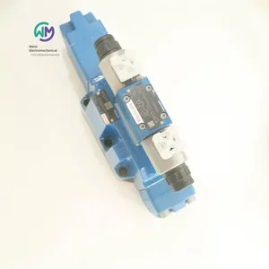
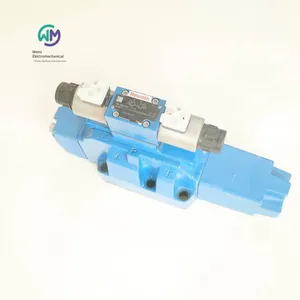
Rexroth Four-way Proportional Valve 4wrz25e325-73/6eg24n9ek4/d3m


Related Products
-
 Rexroth Throttle Valve Z2fs16-8-31/sUS$ 476.92 - 492.31MOQ: 1 Piece
 -
Rexroth Double One-way Throttle Valve Z2fs6-2-46/2qvUS$ 141.54 - 150.77MOQ: 1 Piece
-
Rexroth Proportional Valve 4wrpeh6c3b40l-31/m/24a1US$ 1661.54 - 1692.31MOQ: 1 Piece
-
Rexroth Directional Spool Valve 4weh16d72/6eg24n9ets2k4/b10US$ 453.85 - 461.54MOQ: 1 Piece
-
Bently Vibration Probe 330103-00-05-10-02-00US$ 430.77 - 438.46MOQ: 1 Piece
Rexroth 4-way proportional valve 4WRZ25E325-73/6EG24N9EK4/D3M R900970810, the main product of Shanghai Weimi Mechanical & Electrical Equipment Co., Ltd. Sales hotline: 13524123009; Contact person: Lei Qing; Real-shot product pictures, original and genuine products, in-stock inventory, affordable prices; We sincerely welcome new and old customers to consult and purchase!
Rexroth REXROTH pilot-operated proportional directional valves without electrical position feedback and without integrated electronics (OBE)
4WRZ
Size 10, 16, 25, 32
Component series 7X
Maximum working pressure 350 bar
Maximum flow rate 1600 l/min
Pilot-operated two-stage proportional directional valves without integrated electronics (OBE)
Control the flow direction and flow rate of hydraulic oil
Operated by proportional solenoids with centering threads and detachable coils
For subplate mounting: Hole pattern according to ISO 4401
Auxiliary operating device, optional
Spring-centered control spool
Pilot-operated proportional directional valve models 4WRZ(E)… and 5WRZ(E).52…
Valves of model 4WRZ(E)... are pilot-operated 4-way directional valves actuated by proportional solenoids. Their function is to control the flow direction and flow rate.
Valves of model 5WRZ(E)… are equipped with an additional oil port “R” (limited to NG52).
Configuration:
The basic structure of the valve consists of:
Pilot control valve with proportional solenoid
Main valve with main control spool and centering spring
Function:
After the coil is de-energized, the main control spool will be held in the center position by the centering spring.
The main control spool is controlled by the pilot control valve; the main control spool moves proportionally, for example, by actuating the coil “b”.
→ The control spool moves to the right, and the pilot oil flows into the pressure chamber through the pilot control valve and makes the main control spool rotate proportionally according to the electrical input signal.
→ Connections from P to A and from B to T are made through throttle cross-sections with progressive fluid characteristics
The pilot oil can be supplied to the pilot control valve either internally through port P or externally through port X.
Close the coil
→ The control spool and the main control spool move back to the center position
Depending on the spool position, the hydraulic oil can flow from P to A, from B to T, or from P to B, from A to T (R).
Manual emergency operation is optional, which can be used to move the control spool when the coil is de - energized.
Note:
Accidental activation of the manual emergency operation may lead to uncontrolled machine movement!
Note:
Due to the design principle, there is inherent internal leakage in the valve, and the leakage volume may increase with the service life.
Material numbers and models of German Rexroth electro - hydraulic proportional valves:
R900246980 4WRZ10W8 - 85 - 73/6EG24N9K4/D3M
R900728586 4WRZ16W8 - 150 - 74/6EG24N9K4/D3M
R900939922 4WRZE10W6 - 50 - 7X/6EG24N9K31/F1D3V
R900750127 4WRZE16W8 - 150 - 7X/6EG24N9EK31/A1D3M
R900618031 4WRZE16W8 - 150 - 7X/6EG24N9K31/A1D3M
R900941295 4WRZE16R150 - 7X/6EG24N9K31/A1D3V
R901548124 4WRZE16W6 - 180 - 7X/6EG24N9K31/F1D3M
R900970810 4WRZ25E325 - 73/6EG24N9EK4/D3M
R900712186 4WRZ25E325 - 73/6EG24N9K4/D3M
R900757604 4WRZE25W8 - 220 - 7X/6EG24N9EK31/F1D3M
R901014940 4WRZE25W8 - 325 - 7X/6EG24N9K31/F1D3M
R900763679 4WRZ32W8 - 520 - 73/6EG24N9TK4/D3M
Hydraulic servo control system
It uses servo control elements to complete the control of power and movement direction, integrates pressure, flow and direction control. It uses deviation control to correct errors to meet the needs of precision control and must be a closed - loop control. It can achieve a relatively high frequency (above 100HZ). There are spool valve type, nozzle - baffle type, jet pipe type, etc. Mechanical servo, electro - hydraulic servo and pneumatic - hydraulic servo are often used.
Classification of hydraulic servo systems:
(1) Classified according to the change law of the input signal: there are three types, namely constant - value control system, program control system and servo system. When the input signal of the system is a constant value, it is called a constant - value control system, and its basic task is to improve the anti - interference ability of the system. When the input signal of the system changes according to a pre - given law, it is called a program control system. The servo system is also called a follow - up system, and its input signal is an unknown function of time. The output can accurately and quickly reproduce the change law of the input.
(2) Classification according to different input signals: Mechanical-hydraulic servo systems, electro-hydraulic servo systems, pneumatic-hydraulic servo systems, etc.
(3) Classification according to the output physical quantity: Position servo systems, speed servo systems, force (or pressure) servo systems, etc.
(4) Classification according to control elements: Valve-controlled systems and pump-controlled systems. In mechanical equipment, valve-controlled systems are more widely used.
The characteristics of the hydraulic servo system are as follows:
(1) Feedback. Sending a part or all of the output quantity back to the input end in a certain way and comparing it with the input signal is called feedback. In the above example, the feedback (output of the speed measuring device) voltage and the given (input signal) voltage have opposite signs, that is, the feedback signal continuously cancels out the input signal. This is negative feedback. Most automatic control systems are negative feedback systems.
(2) Deviation. To make the hydraulic cylinder output a certain force and speed, the servo valve must have a certain opening. Therefore, there must be a deviation signal between the input and the output. The movement of the hydraulic cylinder tries to eliminate this error. However, this deviation cannot be completely eliminated at any moment when the servo system is working. The servo system works precisely based on this deviation signal.
(3) Amplification. The force and power output by the actuator (hydraulic cylinder) are far greater than those of the input signal. The output energy is supplied by the hydraulic power source.
(4) Tracking. The output quantity of the hydraulic cylinder completely tracks the change of the input signal.
Rexroth four-way proportional valve 4WRZ25E325-73/6EG24N9EK4/D3M R900970810

Send Inquiry to This Supplier

You May Also Like
-
Rexroth Electro-hydraulic Directional Control Valve 4weh10d47/6eg24n9k4/b10d3US$ 492.31 - 507.69MOQ: 1 Piece
-
Rexroth Directional Slide Valve 4weh16d72/6eg24n9ek4/b10d3US$ 523.08 - 538.46MOQ: 1 Piece
-
Airtec Solenoid Valve Km-10-520-hnUS$ 120 - 123.08MOQ: 1 Piece
-
Rexroth Electro-hydraulic Directional Control Valve 4weh10j47/6eg24n9ets2k4US$ 584.62 - 592.31MOQ: 1 Piece
-
Rexroth Check Valve Z2s6-1-6x/can be Shipped on the Same DayUS$ 76.92 - 92.31MOQ: 1 Piece
-
Aventics Oil Injection Valve 0821300936US$ 76.92 - 80MOQ: 1 Piece
-
Rexroth Check Valve Z1s6d05-40/vUS$ 146.15 - 153.85MOQ: 1 Piece
-
Italian Duplomatic Throttle Valve Mers-d/50US$ 110.77 - 115.38MOQ: 1 Piece
-
Rexroth Check Valve Z1s6t05-40/vUS$ 150.77 - 153.85MOQ: 1 Piece
-
Rexroth Pressure Limiting Valve Dbds30g1a/200-170US$ 243.08 - 246.15MOQ: 1 Unit


