

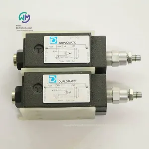
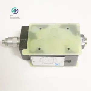
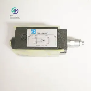
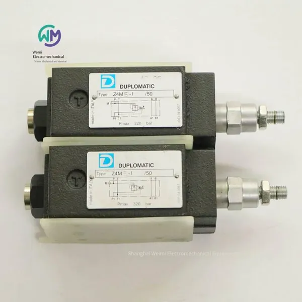
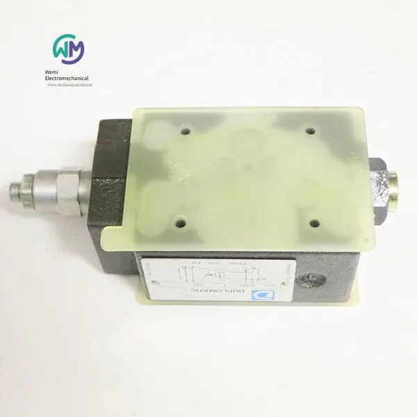
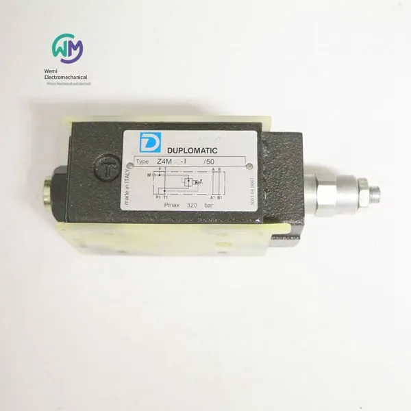
Italian Duplomatic Pressure Reducing Valve Z4m5-i/50
Related Products
-
 Rexroth Hydraulic Proportional Directional Valve R900927235 4wree10v50-23/g24k31/a1vUS$ 1600 - 1630.77MOQ: 1 Piece
 -
German Rexroth Electro-hydraulic Directional Control Valve 4weh16g72/6eg24n9k4US$ 553.85 - 561.54MOQ: 1 Piece
-
Rexroth Proportional Flow Valve Amplifier Board Vt-vrpa1-151-12/v0/0US$ 738.46 - 769.23MOQ: 1 Piece
-
Rexroth Four-way Proportional Valve 4wrz25e325-73/6eg24n9ek4/d3mUS$ 2384.62 - 2461.54MOQ: 1 Piece
-
Rexroth Throttle Valve Z2fs16-8-31/sUS$ 476.92 - 492.31MOQ: 1 Piece
Italian DUPLOMATIC pressure reducing valve Z4M5-I/50, the main product of Shanghai Weimi Mechanical & Electrical Equipment Co., Ltd. Sales hotline: 13524123009; Contact person: Lei Qing; Product real-shot pictures, genuine products from the original factory, in-stock inventory, affordable prices; We sincerely welcome new and old customers to consult and purchase!
Italian DUPLOMATIC pilot-operated pressure reducing valve Z4M series
Stacked type
ISO 4401-05
High working pressure 320 bar
The Z4M stacked valve is a pilot-operated pressure reducing valve, and its mounting surface size conforms to
ISO 4401 (CETOP PR 121H) standard.
This valve can be used to reduce the pressure of the secondary circuit and can ensure the stability of the control pressure, even when the flow rate through the valve changes.
This valve can be quickly installed under the directional valve conforming to ISO 4401-05 (CETOP 05) standard without tubing connection.
It is usually supplied with a countersunk hexagon socket adjustment screw, a lock nut and a maximum adjustment limit device.
This valve can provide 4 different pressure adjustment ranges, with a maximum pressure of 320 bar.
Hydraulic function
Z4M*-I: Pressure reduction in P pipeline, oil drainage at T port.
Z4M*-A: Pressure reduction in A pipeline, full pressure in B pipeline.
Z4M*-B: Pressure reduction in B pipeline, full pressure in A pipeline.
Parameters
Maximum working pressure 320bar
Maximum flow rate of control pipeline P 80l/min
Maximum flow rate of free pipeline 100l/min
Flow rate of oil drainage pipeline ≤0.07l/min
Ambient temperature range -20 / +50℃
Oil temperature range -20 / +80℃
Oil viscosity range 10 ÷ 400cSt
Allowed pollution level of oil According to ISO 4406:1999 level 20/18/15
Recommended oil viscosity 25cSt
Mass 2.7kg
Hydraulic oil
When using mineral hydraulic oil HL or HM conforming to ISO 6743-4 standard, use NBR seals. For HFDR oil (phosphate ester), use FPM seals (code V).
Ordering model of Italian DUPLOMATIC pilot-operated pressure reducing valve:
Z4M5-I/50
Z4M3-I/50
Z4M4-I/50
Duplomatic DUPLOMATIC Proportional Directional Valve DSE3
- Direct-acting proportional directional valve DSE3, with oil ports complying with ISO 4401 (CETOP RP 121H) standard.
- This valve can be used for the direction and speed control of hydraulic actuators.
- The opening and flow rate adjustment of this valve are proportional to the input current of the electromagnet.
- This valve can be directly controlled by the current control supply unit, or combined with an external electrical control card for control, so as to fully utilize the performance of the valve.
- Manual emergency operation with a handle is also available.
Technical parameters (measured under the conditions of using the supporting electrical control unit, at a temperature of 50°C and a hydraulic oil viscosity of 36cSt)
Maximum working pressure:
Oil ports P - A - B 350bar
Oil port T 210bar
Nominal flow rate (P-T pressure difference ΔP = 10bar) 1,3 - 4 - 8 - 16 - 26 l/min
Hysteresis (PWM 200 Hz) % Q max
Repeatability % Q max
Ambient temperature range -20 / +60°C
Oil temperature range -20 / +80°C
Oil viscosity range 10 ÷ 400cSt
Maximum allowable oil pollution degree According to ISO 4406:1999, grade 18/16/13
Recommended oil viscosity 25cSt
Weight:
Single-electromagnet valve 1,6kg
Dual-electromagnet valve 2,0kg
Hydraulic oil
When using mineral hydraulic oil HL or HM complying with ISO 6743-4 standard, use NBR seals (code N). For HFDR oil (phosphate ester), use FPM seals (code V). If using
Other oils, such as HFA, HFB, HFC, please consult us. When the working oil temperature is higher than 80 °C, it will cause the hydraulic oil and seals to age and deteriorate too quickly. Please pay attention to maintaining the stable physical and chemical properties of the hydraulic oil.
Proportional electromagnet
The proportional electromagnet consists of two parts: the iron core and the coil.
The iron core contains the armature, which is installed on the valve body in a threaded form. This design can keep the friction to a minimum, thereby reducing the hysteresis.
The coil is installed on the iron core through a lock nut.
It can be rotated 360° according to the installation space.
Step response refers to the time required for the valve to reach 90% of the set value following the step change of the input reference signal. The typical step response times listed in the table are measured under the condition that the spool function is C16 and the P-T pressure difference Δp = 30 bar.
Step response reference signal 0→100% 100%→0
Step response time ms
DSE3-A* 50
DSE3-C* 40
Installation
Under the condition of not affecting the correct operation, the DSE3 valve can be installed in any direction.
Please ensure that there is no air in the hydraulic circuit.
The valve can be installed on a flat surface by screws or bolts. The flatness and roughness grades of the installation surface must be equal to or higher than the values shown in the figure. If the flatness or roughness fails to meet the required minimum values, oil leakage is likely to occur between the valve and the installation surface.
Manual emergency operation
The manual emergency operation of the standard valve is integrated in the iron core of the electromagnet. A suitable tool must be used for manual emergency operation to avoid damaging the sliding surface of the iron core.
There are four different forms of manual emergency operation to choose from:
- CM type, with a manual emergency protective cover.
- CS type, with a metal ring nut with M4 screws and a lock nut for continuous mechanical operation.
- CH type, handle-type manual emergency operation.
- CK type, knob-type. When the setting screw is tightened until its position is aligned with the edge of the knob, lock the knob until it contacts the spool: in this position, the manual emergency operation will not be activated and the valve is not energized. After adjusting the manual emergency operation, lock the setting screw to prevent the knob from loosening.
Electrical control unit
DSE3 - * * SA (SB)
EDC-112 24V DC electromagnet Plug-in type
EDC-142 12V DC electromagnet Plug-in type
EDM-M112 24V DC electromagnet DIN EN 50022 Rail-mounted type
EDM-M142 12V DC electromagnet DIN EN 50022 Rail-mounted type
UEIK-11 24V DC electromagnet European card type
DSE3 - A* DSE3 - C*
EDM-M212 24V DC electromagnet DIN EN 50022 Rail-mounted type
EDM-M242 12V DC electromagnet DIN EN 50022 Rail-mounted type
UEIK-21 24V DC Electromagnet, European Cartridge Type
Mounting Plate
Model PMMD-AI3G, Bottom Oil Port
Model PMMD-AL3G, Side Oil Port
Thread of P, T, A, B Oil Ports: 3/8” BSP
Ordering Models of Italian DUPLOMATIC Proportional Valves:
DSE3-A26/11N-D24K1
DSE3-A26/11V-D24K1/CK
DSE3-C08/11N-D24K1
DSE3-C08SA/11N-D24K1
DSE3-C16/11N-D24K1
DSE3-C16SA/11N-D24K1
DSE3-C26SA/11N-D24K1
DSE3-C04/11N-D24K1
DSE3J-Z12/20N-E0K11
DSE3J-Z30/15/20N-E0K11
DSE5-A60/10N-D24K1
DSE5-C60/10N-D24K1
DUPLOMATIC Pilot-Operated Proportional Directional Valves, DSPE Series
DSPE5 CETOP P05
DSPE5R ISO 4401-05
DSPE7 ISO 4401-07
DSPE8 ISO 4401-08
DSPE10 ISO 4401-10
The pilot-operated proportional directional valve DSPE* has a mounting surface size that complies with the ISO 4401 (CETOP RP121H) standard.
The adjustment of the valve opening (and thus the resulting flow rate) is proportional to the current input of the proportional solenoid of the pilot valve.
This valve can be directly controlled by a current control supply unit or combined with an external electrical control card for combined control, so as to fully utilize the performance of the valve.
This valve is available in specifications CETOP P05, ISO 4401-05 (CETOP R05), ISO 4401-07 (CETOP 07), ISO 4401-08 (CETOP 08), and ISO 4401-10. Each specification can provide different nominal flow rates, with a maximum flow rate of up to 1600 l/min.
Technical parameters (measured with the supporting electrical control unit at a temperature of 50°C and a hydraulic oil viscosity of 36 cSt)
High working pressure: 350bar
Hysteresis (PWM 100 Hz):
Repeatability:
Ambient temperature range -20/+60℃
Oil temperature range -20/+80℃
Oil viscosity range 10-400cSt
Recommended oil viscosity 25cSt
Characteristic curve (measured under the conditions of a temperature of 50℃ and a hydraulic oil viscosity of 36cSt with the matching electrical control unit)
Under a fixed pressure difference Δp, the typical flow control curve of the valve is measured according to the input current of the electromagnet (Type D24, maximum current 860 mA) through the corresponding spool functions. The reference value of Δp is measured at the P and T ports of the valve.
Hydraulic oil
When using mineral hydraulic oil HL or HM complying with ISO 6743-4 standard, use NBR seals (code N). For HFDR oil (phosphate ester), use FPM seals (code V).
If using other oils, such as HFA, HFB, HFC, please consult our technical department.
When the working oil temperature is higher than 80 °C, it will cause the hydraulic oil and seals to age and deteriorate too quickly.
Please note to maintain the stable physical and chemical properties of the hydraulic oil.
Pilot control and drain oil
DSPE type valves can choose internal or external control and drain. Using external drain allows a higher back pressure at the return port.
Electrical characteristics
Proportional electromagnet
The proportional electromagnet consists of two parts: the iron core and the coil.
The iron core contains the armature, which is installed on the valve body in a threaded form. This design can keep the friction to a minimum, thereby reducing the hysteresis.
The coil is installed on the iron core through a lock nut.
It can be rotated 360° according to the installation space.
Step response (measured under the conditions of a temperature of 50℃ and a hydraulic oil viscosity of 36cSt with the matching electrical control unit)
The step response refers to the time required for the valve to reach 90% of the set value following the step change of the input reference signal.
Installation
Under the condition of not affecting the correct operation, the DSPE* valves can be installed in any direction.
Please ensure that there is no air in the hydraulic circuit.
The valve can be installed on a flat surface by screws or bolts. The flatness and roughness grades of the installation surface must be equal to or higher than the values shown in the figure. If the flatness or roughness does not reach the required minimum value, oil leakage is likely to occur between the valve and the installation surface.
Diplomatic DUPLOMATIC proportional valve models:
DSPE7-A150/11N-II/D24K1
DUPLOMATIC Electro-hydraulic Servo Valves with Integrated Amplifier Boards, DXJ3 Series
Panel Mounting
ISO 4401-03 (CETOP 03)
Maximum Operating Pressure 350 bar
The spool of the four-way servo proportional valve DXJ3 moves within the valve sleeve. The valve is directly driven by a linear force motor, resulting in high dynamic performance independent of the system pressure. The spool displacement is controlled in a closed-loop by a linear sensor (LVDT), ensuring high precision and repeatability.
The valve is available in four different flow control ranges, up to 40 l/min. The spool has zero overlap, and the mounting surface dimensions comply with ISO 4401 (CETOP RP121H) standards.
The valve is characterized by its integrated amplifier board based on SMD technology, which ensures standard adjustment and simple electrical wiring. Except for possible electrical zero adjustment, the amplifier board does not require any adjustment.
Suitable for closed-loop control applications of position, speed, and pressure. When the power is off or the reference input signal is zero, the spool automatically returns to the neutral position. At this position, the valve has a small leakage, depending on the operating pressure (see the technical parameter table).
External leakage type is available.
Technical parameters (measured at an oil temperature of 50℃ and a hydraulic oil viscosity of 36cSt)
Nominal Flow Rate 5-10-20-40l/min
Zero Leakage (at p = 140 bar) l/min ≤ 3% Q nom
Hysteresis
Threshold
Temperature Drift (∆T = 50°C)
Response Time ≤ 12ms
Three-axis Vibration 30g
Protection Class in Compliance with CEI EN 60529 IP 65
Ambient Temperature Range -20/+60°C
Oil Temperature Range -20/+80℃
Oil Viscosity Range 5 - 400cSt
Maximum Allowed Oil Pollution Degree According to ISO 4406:1999 Grade 17/15/12
Recommended Oil Viscosity 25cSt
Mass 2.5kg
Electrical Characteristics
General Requirements:
External Fuse = 1,6 A
Minimum Cross-sectional Area of All Wires ≈0,75 mm2
When making electrical connections for the valve (shielding, grounding protection), appropriate measures must be taken to ensure that excessive grounding current is not caused by different local grounding potentials.
The differential signal line and the spool position signal line must be connected to the matching plug protective cover on the valve side and the 0V (signal ground) on the electrical control box side.
EMC: Meets the requirements of EN 55011:1998, Class B, and the anti-interference adjustment complies with EN 61000-6-2:1998.
Hydraulic oil
When using mineral hydraulic oil HL or HM that complies with ISO 6743-4 standard, use NBR seals. For HFDR oil (phosphate ester), use FPM seals (code V). If using other oils, such as HFA, HFB, HFC, please consult our technical department. When the working oil temperature is higher than 80 °C, it will cause the hydraulic oil and seals to age and deteriorate rapidly.
Please note to maintain the stable physical and chemical properties of the hydraulic oil.
Installation
Under the condition that it does not affect the correct operation, the DXJ3 valve can be installed in any direction.
The valve can be installed on the installation surface with a flatness range of 0,01/100mm and a roughness Ra
Ordering model of Italian DUPLOMATIC servo valve:
DXJ3-D0L20/10N/E0K11
Italian DUPLOMATIC electro-hydraulic servo valve with integrated amplifier board, DXJ5 series
Plate installation ISO 4401-05 (CETOP R05)
Maximum working pressure 350 bar
The spool of the four-way servo proportional valve DXJ5 moves inside the valve sleeve. This valve is directly driven by a linear force motor to obtain high dynamic performance independent of the system pressure. The spool displacement is controlled by a linear sensor (LVDT) in a closed-loop manner to ensure high precision and repeatability.
This valve can provide two different flow control ranges, up to 100 l/min. The spool has zero overlap, and the installation surface size complies with the ISO 4401 (CETOP RP 121H) standard.
The feature of this valve is that its integrated amplifier board is based on SMD technology, which can ensure standard adjustment and simple electrical wiring. Except for possible electrical zero adjustment, this amplifier board does not require any adjustment.
It is suitable for closed-loop control applications of position, speed and pressure. When the power is off or the reference input signal is zero, the spool automatically returns to the neutral position. In this position, the valve has a small leakage amount, which depends on the working pressure.
External leakage type is available.
Technical parameters (measured at an oil temperature of 50°C and a hydraulic oil viscosity of 36cSt)
High working pressure
P - A - B port 350bar
T port (standard) 50bar
T port with Y port 350bar
Nominal flow rate Qnom (P-T pressure difference Δp 70) 60 - 100l/min
Zero leakage (at p = 140 bar) l/min ≤ 3% Q nom
Hysteresis
Threshold
Temperature drift (at ΔT = 50°C)
Response time ≤ 20ms
Three-axis vibration 30g
Protection level in line with CEI EN 60529 IP 65
Ambient temperature range -20/+60℃
Hydraulic oil temperature range -20/+80℃
Hydraulic oil viscosity range 5 - 400cSt
Permissible high pollution degree of hydraulic oil According to ISO 4406:1999 grade 17/15/12
Recommended hydraulic oil viscosity 25cSt
Weight 6.3kg
Electrical characteristics
External fuse = 2.5 A
Minimum cross-sectional area of all wires ≈ 0.75 mm2
When making the electrical connection of the valve (shielding, grounding protection), appropriate measures must be taken to ensure that excessive grounding current will not be caused by different local grounding potentials.
The differential signal wire and the spool position signal wire must be connected to the matching plug shield on the valve side and the 0V (signal ground) on the electrical control box side.
EMC: Meets the requirements of EN 55011:1998, Class B, and the anti-interference adjustment complies with EN 61000-6-2:1998.
Hydraulic oil
When using mineral hydraulic oil HL or HM that meets the ISO 6743-4 standard, use NBR seals. For HFDR oil (phosphate ester), use FPM seals (code V). If other oils such as HFA, HFB, HFC are used, please consult our technical department. When the working oil temperature is higher than 80 °C, it will cause the hydraulic oil and seals to age and deteriorate too quickly. Please pay attention to maintaining the stable physical and chemical properties of the hydraulic oil.
Installation
Under the condition that it does not affect the correct operation, the DXJ5 valve can be installed in any direction. The valve can be installed on the installation surface with a flatness range of 0.01/100mm and a roughness Ra
Dupomatic DUPLOMATIC servo valve order model:
DXJ5-D0L060/10N/E0K11
DXJ5-D0L100/10N/E0K11
DXJ5-D0L100/10N/E1K11
Dupomatic DUPLOMATIC pilot-operated proportional relief valve PRE
Plate installation
Maximum working pressure: 350 bar
- The pilot-operated proportional relief valve PRE* has a mounting surface size that complies with ISO 6264 standard (CETOP RP 121H). - This series of valves is usually used to control the pressure of the hydraulic circuit. Even when the setting is close to the calibrated value, the full flow of the pump can be used.
- Its two-stage design and wide flow channels ensure a reduced pressure drop, thereby improving the energy consumption performance of the system.
- The pressure adjustment is proportional to the input current of the electromagnet.
- This valve can be directly controlled by the current control supply unit or combined with an external electrical control card for combined control to fully utilize the performance of the valve. - This series of valves is equipped with a manual relief valve, and its factory setting is ≥15% of the maximum value within the pressure control range.
- This series of valves can provide three specifications with a maximum flow rate of up to 500 l/min and four pressure control ranges, up to 350 bar.
Technical parameters (measured under the conditions of a supporting electrical control unit, at a temperature of 50°C and a hydraulic oil viscosity of 36cSt)
Type PRE10 PRE25 PRE32
Maximum working pressure: 350bar
Maximum flow rate: 200l/min 400l/min 500l/min
Hysteresis % of p nom
Repeatability % of p nom
Ambient temperature range -20 / +60°C
Oil temperature range -20 / +80°C
Oil viscosity range 10 - 400cSt
Maximum allowable oil pollution degree According to ISO 4406:1999 grade 18/16/13
Recommended oil viscosity 25cSt
Weight: 5kg 5.8kg 8kg
Hydraulic oil
When using mineral hydraulic oil HL or HM that complies with ISO 6743-4 standard, use NBR seals (code N). For HFDR oil (phosphate ester), use FPM seals (code V). When the working oil temperature is higher than 80 °C, it will cause the hydraulic oil and seals to age and deteriorate too quickly.
Please note to maintain the stable physical and chemical properties of the hydraulic oil.
Proportional electromagnet
The proportional electromagnet consists of two parts: the iron core and the coil.
The iron core contains an armature, which is installed on the valve body in the form of a thread. This design can keep the friction to a minimum, thereby reducing the hysteresis loop.
The coil is installed on the iron core through a lock nut and can be rotated 360° according to the installation space.
Step response
The step response refers to the time required for the valve to reach 90% of the set value following the step change of the input reference signal.
Step response reference signal 0→100% 100→0%
Step response time 120ms 90ms
Installation
We recommend installing the PRE* valve horizontally or vertically with the electromagnet facing down. If the valve is installed vertically with the electromagnet facing up, the possibility of a change in the minimum control pressure must be considered.
Please ensure that there is no air in the hydraulic circuit. In some special applications, the air entrained in the iron core must be discharged by using the appropriate exhaust bolt in the electromagnet iron core. After the operation, make sure to tighten the exhaust bolt correctly.
Connect the T port of the valve directly to the oil tank. The control pressure value must be added with any back pressure value detected at the T port. Under normal operating conditions, the maximum allowable back pressure at the T port is 2 bar.
The valve can be installed on a flat surface by screws or bolts. The flatness and roughness grade of the installation surface must be equal to or higher than 0.01/100. If the flatness or roughness does not reach the required minimum value, oil leakage is likely to occur between the valve and the installation surface.
Electrical control unit
EDC - 112 24V DC electromagnet Plug-in type
EDC - 142 12V DC electromagnet Plug-in type
EDM - M112 24V DC electromagnet DIN EN 50022 rail-mounted
EDM - M142 12V DC electromagnet DIN EN 50022 rail-mounted
UEIK - 11 24V DC electromagnet European card type
Installation plate
Type PRE10 PRE25 PRE32
Installation plate model PMRQ3 - AI4G bottom oil port PMRQ5 - AI5G bottom oil port PMRQ7 - AI7G bottom oil port
P, T oil port size P: 1/2” BSP; T: 3/4” BSP, 1” BSP, 1” ¼ BSP
X port size 1/4” BSP 1/4” BSP 1/4” BSP
DUPLOMATIC Pilot-operated proportional relief valve model:
PRE10-210/20N-D24K1
PRE10-350/20V-D24K1
PRE10-350/10N-D24K1
PRE10-350/20N-D24K1
DUPLOMATIC Charge valve
Plate-type installation
High working pressure 350 bar
- The hydraulic control pilot valve CFP is specially designed for hydraulic presses, allowing the pressure oil cylinder to quickly fill and release oil during the rapid upward and downward strokes.
- This valve is "sandwich-type" installed and can be directly installed between the oil suction flange (connected to the oil tank) and the oil cylinder.
- A pre-opening device connected to the X pilot oil port can be provided, allowing the oil circuit to relieve pressure before the upward stroke of the hydraulic cylinder starts.
- The CFP valve is available in 7 different specifications, with a maximum flow rate of up to 2500l/min.
Technical parameters
Valve parameters CFP-S032 CFP-S040 CFP-S050 CFP-S063 CFP-S080 CFP-S100 CFP-S125
Nominal size DN-32 DN-40 DN-50 DN-63 DN-80 DN-100 DN-125
Maximum flow rate (when the pressure difference ∆p = 0.3 bar and the oil viscosity is 36cSt) 160l/min 250l/min 400l/min 600l/min 1000l/min 1600l/min 2500l/min
Maximum pressure:
Port P and B 350bar
Port X 100bar
Port A 16bar
Weight 1.2kg 1.7kg 2.5kg 3.5kg 5.2kg 12kg 20kg
Ambient temperature range –20 / +50°C
Oil temperature range –20 / +80°C
Oil viscosity range 10-400cSt
Recommended oil viscosity 25cSt
The maximum allowable pollution level of the oil is Grade 20/18/15 according to ISO 4406:1999
Hydraulic oil
When using mineral hydraulic oil HL or HM that complies with ISO 6743-4 standard, use NBR seals. For HFDR oil (phosphate ester), use FPM seals (code V). When the working oil temperature is higher than 80 °C, it will cause the hydraulic oil and seals to age and deteriorate rapidly.
Ordering model of Italian DUPLOMATIC filling valve:
CFP-S040/0/10N
DUPLOMATIC pressure sensor PTH series
High working pressure 40 - 100 - 250 - 400 bar
Instructions for use
This series of pressure sensors are mainly used in industrial applications and mobile machinery.
The main feature of this sensor is that it can ensure the stability of its functions under harsh working conditions, especially in terms of the applicable oil working temperature range, which can range from as low as -40°C to as high as +120°C.
This sensor is designed based on the force-strain principle and uses SMT technology to supply power to the circuit, ensuring its high stability and the ability to resist fluctuations and the influence of external mechanical pressure.
Each component in contact with the oil is made of stainless steel, and the entire pressure sensor is oil-proof.
The electrical connection protection level of the sensor with a DIN-type connection plug is IP65, while that of the sensor with an M12-type connection plug can reach IP67.
This series of sensors can provide a current output signal of 4 - 20 mA or a voltage output signal of 0 - 10 V, and also have reverse polarity protection.
From 40 bar to 400 bar, this series of sensors can provide 4 different pressure ranges.
Technical parameters
Nominal pressure PN 40-100-250-400 bar
High dynamic pressure 75% PN
Maximum pressure 200% PN
Accuracy class 0,5% PN
Output signal
Voltage 0...10V
Current 4...20mA
Response time
Hysteresis ± 0,2% PN
Repeatability accuracy ± 0,05% PN
Linearity ± 0,2% PN
Stability (after 1 million cycles) ± 0,1% PN
Working temperature range - 40/+120℃
Thermal drift from 0 to +100 °C ± 1% PN
Compliant with EC standards. Radiation: 61000-6-3, Immunity: 61000-6-2
Variable resistance > 20 G
Pressure interface: G 1/4” with integrated seal
Electrical connection
K10 connection: 3-pole + grounding, DIN 43650 simple plug
K12 connection (available upon request): M12x1 4-pin straight plug
Protection class (EN 60529). K10 connection: IP 65; K12 connection: IP 67
Ambient temperature range. K10 connection: - 20/+ 80℃; K12 connection: - 25/+85℃
Housing material: AISI 304
Weight: 0.1kg
Sensor voltage
PTH-*/20E0-*
This type of sensor is equipped with a voltage regulator, which can provide a stable voltage for the circuit and is not dependent on the voltage supplied by the power source.
We recommend a stable power supply voltage of 24 VDC.
PTH-*/20E1-*
The recommended power supply voltage is 24 VDC, and the load resistance is 700 Ohm.
DUPLOMATIC pressure sensor models:
PTH-250/30V-E0K10
Italian DUPLOMATIC pilot-operated check valve CHM2 series
Serial number: 10
The CHM2 valve is a stacked hydraulically controlled check valve, which is closed by a spring and sealed by a cone valve core. Its installation dimensions comply with ISO 4401 (CETOP RP 121H) standards.
The main functions of this valve are:
- Prevent the flow of oil in one direction;
- If the pilot pressure opens the valve, allow the oil to flow in the above direction;
- Allow the oil to flow freely in the other direction.
The CHM2 valve is usually installed under the DL2 solenoid directional valve (see sample
411000), and can also be combined with other valves that comply with ISO 4401-02 (CETOP R02)
standards to form a stacked valve group.
Technical parameters (measured at an oil temperature of 50°C and an oil viscosity of 36 cSt)
Maximum working pressure: 320 bar
Maximum flow rate: 30 l/min
Pressure ratio between the sealed chamber and the pilot port: 3.5 :1
Check valve opening pressure: 2bar
Ambient temperature range -20/+50℃
Oil temperature range -20/+80℃
Oil viscosity range 10 ÷ 400cSt
Recommended oil viscosity 25cSt
Maximum allowable pollution level of the oil According to ISO 4406:1999, grade 20/18/15
Weight 0.75kg
Hydraulic oil
When using mineral hydraulic oil HL or HM that complies with ISO 6743-4 standard, use NBR seals. For HFDR oil (phosphate ester), use FPM seals (code V).
If using other oils, such as HFA, HFB, HFC, etc., please consult our technical department.
When the working oil temperature is higher than 80 °C, it will cause the hydraulic oil and seals to age and deteriorate rapidly.
Please note to maintain the stable physical and chemical properties of the hydraulic oil.
Italian DUPLOMATIC Pilot-operated Check Valve CHM5 Series
Stacked ISO 4401-05 (CETOP 05)
This valve is a stacked hydraulically controlled check valve (spring-closed and cone valve core sealing). Its mounting surface dimensions comply with ISO 4401 (CETOP RP 121H) standard.
The CHM5 valve is usually installed under the electromagnetic directional valve that complies with ISO 4401-05 (CETOP 05) standard, and can also be combined with other valves that comply with ISO 4401-05 (CETOP05) standard to form a stacked valve group.
The pre-opening characteristic of the valve can relieve the pressure in the hydraulic cylinder chamber, thus enabling it to move more smoothly.
Technical parameters (measured at an oil temperature of 50°C and an oil viscosity of 36 cSt)
Maximum working pressure 320 bar
Maximum flow rate 120 l/min
Pressure reduction ratio 14,9:1
Pilot ratio 2,3:1
Check valve opening pressure 2bar
Ambient temperature range -20/+50℃
Oil temperature range -20/+80℃
Oil viscosity range 10 ÷ 400cSt
Recommended oil viscosity 25cSt
Maximum allowable pollution level of the oil According to ISO 4406:1999, grade 20/18/15
Weight 2.2kg
Hydraulic oil
When using mineral hydraulic oil HL or HM that complies with ISO 6743-4 standard, use NBR seals. For HFDR oil (phosphate ester), use FPM seals (code V).
If you use other hydraulic fluids, such as HFA, HFB, HFC, etc., please consult our technical department.
When the working oil temperature is higher than 80 °C, it will cause the hydraulic oil and seals to age and deteriorate too quickly.
Please note to maintain the stable physical and chemical properties of the hydraulic oil.
Ordering models of DUPLOMATIC pilot-operated check valves:
CHM5-SA/10N
CHM5-SB/10N
CHM5-D/10N
Italian DUPLOMATIC pressure reducing valve Z4M5-I/50

Send Inquiry to This Supplier

You May Also Like
-
Rexroth Double One-way Throttle Valve Z2fs6-2-46/2qvUS$ 141.54 - 150.77MOQ: 1 Piece
-
Rexroth Proportional Valve 4wrpeh6c3b40l-31/m/24a1US$ 1661.54 - 1692.31MOQ: 1 Piece
-
Rexroth Directional Spool Valve 4weh16d72/6eg24n9ets2k4/b10US$ 453.85 - 461.54MOQ: 1 Piece
-
Bently Vibration Probe 330103-00-05-10-02-00US$ 430.77 - 438.46MOQ: 1 Piece
-
Rexroth Electro-hydraulic Directional Control Valve 4weh10d47/6eg24n9k4/b10d3US$ 492.31 - 507.69MOQ: 1 Piece
-
Rexroth Directional Slide Valve 4weh16d72/6eg24n9ek4/b10d3US$ 523.08 - 538.46MOQ: 1 Piece
-
Airtec Solenoid Valve Km-10-520-hnUS$ 120 - 123.08MOQ: 1 Piece
-
Rexroth Electro-hydraulic Directional Control Valve 4weh10j47/6eg24n9ets2k4US$ 584.62 - 592.31MOQ: 1 Piece
-
Rexroth Check Valve Z2s6-1-6x/can be Shipped on the Same DayUS$ 76.92 - 92.31MOQ: 1 Piece
-
Aventics Oil Injection Valve 0821300936US$ 76.92 - 80MOQ: 1 Piece


