

Rexroth Proportional Flow Valve Amplifier Board Vt-vrpa1-151-12/v0/0

Related Products
-
 Rexroth Four-way Proportional Valve 4wrz25e325-73/6eg24n9ek4/d3mUS$ 2384.62 - 2461.54MOQ: 1 Piece
 -
Rexroth Throttle Valve Z2fs16-8-31/sUS$ 476.92 - 492.31MOQ: 1 Piece
-
Rexroth Double One-way Throttle Valve Z2fs6-2-46/2qvUS$ 141.54 - 150.77MOQ: 1 Piece
-
Rexroth Proportional Valve 4wrpeh6c3b40l-31/m/24a1US$ 1661.54 - 1692.31MOQ: 1 Piece
-
Rexroth Directional Spool Valve 4weh16d72/6eg24n9ets2k4/b10US$ 453.85 - 461.54MOQ: 1 Piece
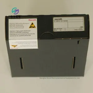
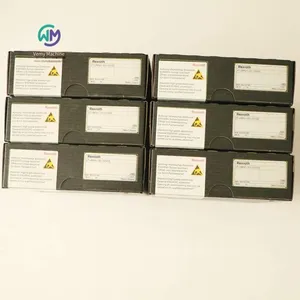
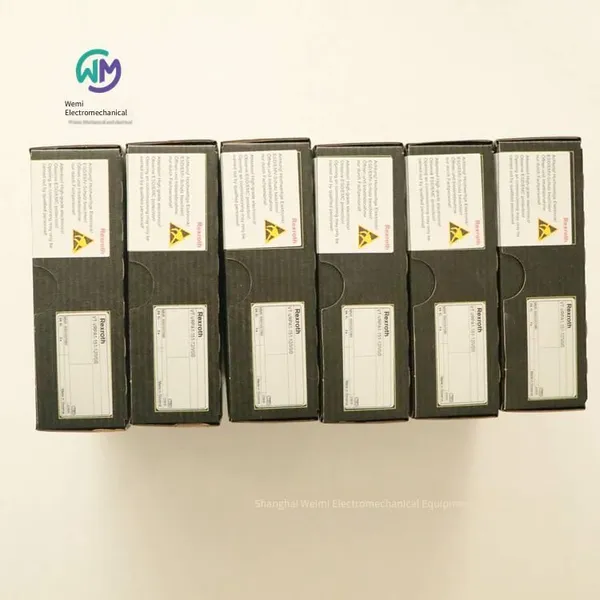
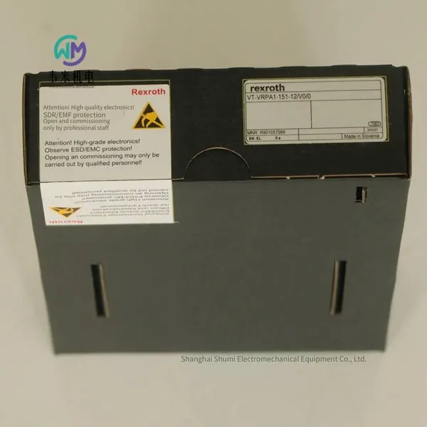
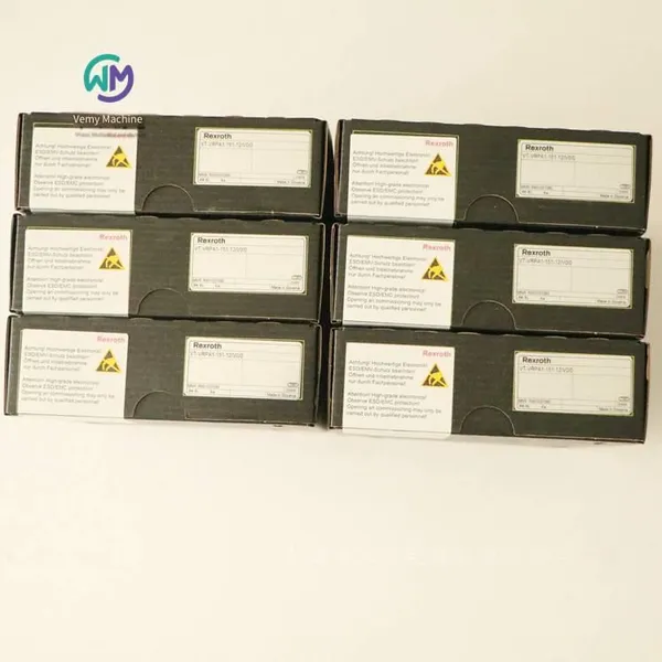
Rexroth proportional flow valve amplifier board VT-VRPA1-151-12/V0/0 R901057060, the main product of Shanghai Weimi Mechanical & Electrical Equipment Co., Ltd. Sales hotline: 13524123009; Contact person: Lei Qing; Real product photos, original and genuine products, in-stock inventory, affordable price. We sincerely welcome new and old customers to consult and purchase!
Rexroth REXROTH proportional flow valve amplifier
VT-VRPA1-151-1X
R901057060 VT-VRPA1-151-11/V0/0
R901057060 VT-VRPA1-151-12/V0/0
Component series 1X
Analog, European board format
For valves: 2FRE 10, 2FRE 16
Differential input, convertible from voltage input to current input
Two non-insulated control value inputs
Strobe input and "ramp off" input
Amplitude, zero potential and adjustable ramp time
Reverse polarity protection for operating voltage
Output of control value and theoretical value
"Ready" LED display
Limiter and position controller
When outputting from the ramp generator, the control value voltage will reach the "Gw" potentiometer, which can be used through the panel and serves as an attenuator. It can also be used to set the large filling flow of the valve. The downstream limiter limits the control value to 105% to -5% (for example, under excessive control value voltage or by adjusting the zero position "Zw" and the basic value "Gw" of the potentiometer) to prevent the spool from hitting the mechanical end position. The output signal of the limiter is the position control value, which will be provided to the PID controller and through the output stage to the measurement socket "w" on the board panel and port 28c of the connector board X1 (the control value after ramp and limiting). The +6 V voltage of the control value measurement socket "w" corresponds to a control value of +100%. The PID controller is specially optimized for DBRTE and FRE valves. In the controller, the position control value will be compared with the actual position value; if there is a difference, the corresponding control output will be fed forward to the current output stage to control the output signal of the valve proportional electromagnet.
Position detection
The position sensor electronics include an oscillator with a downstream driver for controlling the inductive position sensor and a demodulator for analyzing the position sensor signal (theoretical value). The oscillator frequency is approximately 2.5 kHz. The inductive position sensor must be connected as a throttle circuit with "intermediate" sensing. The position sensor electronics are adjusted at the factory. Longer wires or wires of capacitive position sensors may require re-adjustment of the zero position (through the potentiometer "Zx"). The theoretical value (corresponding to the spool position) can be measured at the actual value measurement socket.
Note:
Compared with the control value, the actual value signal will be output in reverse form. A 100% path corresponds to -6 V at the theoretical value measurement socket and port 32a of connector board X1.
Strobe input
Enable the output stage and the I controller (indicated by the yellow LED on the panel) by a signal of > 10 V at strobe input 20a. They can be enabled individually by using the signal of the strobe input through setting jumper X3. Subsequent conversion inputs will be invalid.
[ ] = Assignment to the circuit diagram
When using an external time potentiometer, the internal potentiometer for the ramp time must be set to a large value (the voltage at the "t1" and "t2" measurement sockets is approximately 20 mV). When the resistance value of the external potentiometer is connected in parallel with that of the internal potentiometer (approximately 500 kΩ), the maximum ramp time will decrease. In this case, the ramp times for the rising and falling ramps cannot be set separately.
Set the ramp time to a minimum value (approximately 15 ms) by applying a voltage of > 10 V to the "Ramp off" conversion input or setting the plug-in jumper X4. Subsequent conversion inputs will be invalid. The minimum value is valid for both directions.
Calculation of the ramp time
Jumper X9 plug (ramp time "short")
Jumper X8 plug (ramp time "long")
The following applies:
U = Voltage at the measurement socket in volts "t1" or "t2"
t = Ramp time for the rising and falling ramps in seconds
Ramp function
The downstream ramp generator [3] generates a ramp-shaped output signal based on the given step input signal. The time constant (ramp time) of the output signal can be adjusted using the "t1" (rising ramp) and "t2" (falling ramp) potentiometers on the panel. The maximum ramp time refers to a 100% control value step. Depending on the jumper settings (X8, X9), this time can be approximately 5 s or 50 s. If a control value step of less than 100% is converted to the ramp generator input, the ramp time will be shortened accordingly. The current ramp time can be checked at the measurement sockets of "t1" (rising ramp) and "t2" (falling ramp).
Power supply device
After applying the operating voltage, the internal power supply device will generate a voltage of ±9 V compared to the measurement zero (M0). It is increased by +9 V based on the measurement of the load zero (L0). The voltages +9 V and -9 V (-9 V corresponds to L0) flow into connector board X1 and are used externally (e.g., for the control value potentiometer). The maximum load capacity is 25 mA.
Ready
The amplifier board will be ready if the following conditions are met:
Operating voltage > 20 V
Asymmetry of internal power supply voltage
No cable interruption in the position sensor wire
No short circuit in the coil wire
The "Ready" status is indicated by the green LED on the panel.
Control value
The control value voltage is directly supplied by the regulated voltage +9 V of the power supply device [6] or through an external control value potentiometer. For the "Control value 1" input, +9 V ≙ +100 %; for the "Control value 2" input, +6 V ≙ +100 %. The reference points 1 and 2 for the control value inputs are always M0 (18ac). The control value input 3 is a differential input (0 to +10 V). It can be configured as a current input (0 to 20 mA or 4 to 20 mA) by setting the jumper. If the control value is provided by external electronic components with different reference potentials, a differential input must be used.
When disconnecting or connecting the control value voltage, ensure that in any case, both signal lines are disconnected from the input simultaneously or connected to it simultaneously. All control values will be accumulated according to their values and signs before feed - forward. The "Zw" potentiometer can be used to compensate for the offset voltage in the control value voltage division.
Rexroth proportional flow valve amplifier board VT - VRPA1 - 151 - 12/V0/0 R901057060

Send Inquiry to This Supplier


You May Also Like
-
Bently Vibration Probe 330103-00-05-10-02-00US$ 430.77 - 438.46MOQ: 1 Piece
-
Rexroth Electro-hydraulic Directional Control Valve 4weh10d47/6eg24n9k4/b10d3US$ 492.31 - 507.69MOQ: 1 Piece
-
Rexroth Directional Slide Valve 4weh16d72/6eg24n9ek4/b10d3US$ 523.08 - 538.46MOQ: 1 Piece
-
Airtec Solenoid Valve Km-10-520-hnUS$ 120 - 123.08MOQ: 1 Piece
-
Rexroth Electro-hydraulic Directional Control Valve 4weh10j47/6eg24n9ets2k4US$ 584.62 - 592.31MOQ: 1 Piece
-
Rexroth Check Valve Z2s6-1-6x/can be Shipped on the Same DayUS$ 76.92 - 92.31MOQ: 1 Piece
-
Aventics Oil Injection Valve 0821300936US$ 76.92 - 80MOQ: 1 Piece
-
Rexroth Check Valve Z1s6d05-40/vUS$ 146.15 - 153.85MOQ: 1 Piece
-
Italian Duplomatic Throttle Valve Mers-d/50US$ 110.77 - 115.38MOQ: 1 Piece
-
Rexroth Check Valve Z1s6t05-40/vUS$ 150.77 - 153.85MOQ: 1 Piece