








 Contact Platform Support
 Help Center
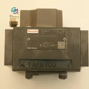
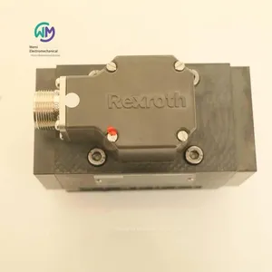
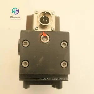
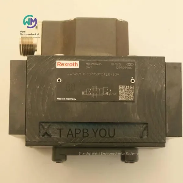
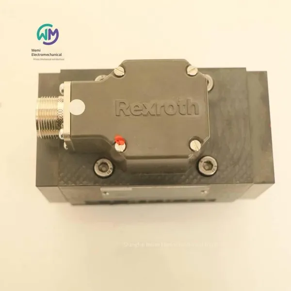
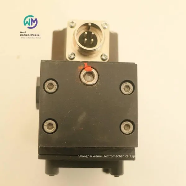
Rexroth Four-way Servo Valve 4ws2em10-52/75b11et315k8dv



Related Products
-
 Italian Duplomatic Pressure Reducing Valve Z4m5-i/50US$ 223.08 - 227.69MOQ: 1 Piece
 -
Rexroth Hydraulic Proportional Directional Valve R900927235 4wree10v50-23/g24k31/a1vUS$ 1600 - 1630.77MOQ: 1 Piece
-
German Rexroth Electro-hydraulic Directional Control Valve 4weh16g72/6eg24n9k4US$ 553.85 - 561.54MOQ: 1 Piece
-
Rexroth Proportional Flow Valve Amplifier Board Vt-vrpa1-151-12/v0/0US$ 738.46 - 769.23MOQ: 1 Piece
-
Rexroth Four-way Proportional Valve 4wrz25e325-73/6eg24n9ek4/d3mUS$ 2384.62 - 2461.54MOQ: 1 Piece
Rexroth 4-way servo valve 4WS2EM10-52/75B11ET315K8DV, the main product of Shanghai Weimi Mechanical & Electrical Equipment Co., Ltd. Sales hotline: 13524123009; Contact person: Lei Qing; Product real-shot pictures, original genuine products, in-stock inventory, affordable prices; We sincerely welcome new and old customers to consult and purchase!
Rexroth REXROTH 4-way directional servo valve
4WS.2E...
R901066145 4WS2EM10-52/75B11ET315K8DV
Specification 10
Component series 5X
Maximum working pressure 315 bar
Maximum flow rate 180 l/min
Valve for controlling position, force, pressure or rate
Two-stage servo valve with mechanical feedback or mechanical and electrical feedback
1st stage nozzle/flapper amplifier
For subplate mounting: Hole pattern according to ISO 4401
Dry control motor, the hydraulic fluid must not contaminate the electromagnet gap
Also used as a 3-way structure
Wear-free control spool reset element
Controlled externally or through integrated electronics (OBE)
The valve and integrated control electronics have been adjusted and tested
Control spool with hydraulic force compensation
Centrally fixed control valve sleeve, so it is less sensitive to temperature and pressure
The pressure chamber on the control valve sleeve has a clearance seal, so there is no seal wear
The filter of the 1st stage can be freely serviced from the outside
Product description
4WS(E)2EM10-5X/...
The 4WS(E)2EM10-5X type valves are electrically operated 2-stage servo directional valves. They are mainly used for controlling position, force and rate.
These valves consist of an electromechanical converter (torque motor), a hydraulic amplifier (principle: nozzle flapper) and a control spool in the sleeve (2nd stage) (connected to the torque motor through mechanical feedback).
The electrical input signal on the torque motor coil generates a force acting on the armature through the magnet and together with the elastic tube generates a torque. This causes the flapper bolted to the elastic tube to move from the central position between the two control nozzles, and a pressure difference is generated on the front side of the control spool. This pressure difference causes the control spool to change position, and causes the pressure port to connect to an actuator port. At the same time, the other actuator port is connected to the return port.
The control spool is connected to the flapper or the torque motor through a bending spring (mechanical feedback). The position of the control spool will change until the feedback torque of the bending spring and the electromagnetic torque of the torque motor reach equilibrium and the pressure difference of the nozzle flapper system becomes zero.
Therefore, the stroke of the control spool and the flow rate of the servo valve are controlled in proportion to the electrical input signal. It must be noted that the flow rate depends on the valve pressure drop.
External control electronics, type 4WS2EM10-5X/... (to be ordered separately)
The external control electronics (servo amplifier) operate the valve and amplify the analog input signal (control value) to drive the servo valve in the form of flow control through the output signal.
Integrated control electronics, type 4WSE2EM10-5X/... and type 4WSE2ED10-5X/...
To amplify the analog input signal, the control electronics (10) specifically adjusted for this valve type need to be integrated. They are connected to the torque motor cap. The valve zero position can be adjusted via an externally accessible potentiometer.
4WSE2ED10-5X/...
For mechanical control via a return spring, this type of valve is also equipped with an electrical spool position detection and control device. The position of the control spool is determined by an inductive position sensor. The integrated control electronics compare the position sensor signal with the control value. Any possible control deviation is electrically amplified and fed as a control signal to the torque motor. With additional electrical feedback, compared with the pure mechanical model, the electrical controller amplification rate can achieve a higher dynamic value in a smaller signal range. The additional mechanical feedback provided ensures that the spool is in the zero range in case of a power failure.
The valve is only used in conjunction with the integrated control electronics. The valve zero position can be adjusted via an externally accessible potentiometer.
Note: Changing the zero potential may cause system damage and can only be performed by professional personnel.
Order numbers and models of REXROTH servo valves from Germany:
R901066145 4WS2EM10-5X/75B11ET315K8DV
R901065784 4WS2EM10-52/20B11ET315K8DV
R900956874 4WS2EM10-52/30B11ET315K31DV
R901020256 4WS2EM10-52/60B11ET315K8DV
R900952165 4WSE2EM6-22/5B9ET315K17EV
REXROTH solenoid-operated 2/3-way and 2/4-way directional seat valves
M-.SED 10
Size 10
Component series 1X
Maximum working pressure 350 bar
Maximum flow rate 40 l/min
Features
Solenoid-operated direct-acting directional seat valve
Base plate (to be ordered separately)
The blocked connection is in a sealed state
It can still be safely switched on and off after long-term idling under pressure
Wet pin DC coil with detachable coil (a rectifier must be installed if it is an AC power supply)
The electromagnetic coil can be rotated by 90°
There is no need to open the pressure-resistant sealed cavity when replacing the coil
The electrical connection is made as a single connection
With hidden manual emergency control, optional
Position induction switch and proximity sensor (contactless)
2/3-way directional seat valve
The directional valve of model M-.SED is a direct-acting directional seat valve operated electromagnetically. This valve controls the start, stop and direction of the fluid and is mainly composed of a housing, a coil, a valve seat and a closing element.
Manual emergency operation allows the valve to be switched without energizing the coil.
Basic principle
The initial position of the valve (normally open "UK" or normally closed "CK") is determined by the arrangement of the spring. The cavity behind the closing element is connected to port P and is sealed off from port T.
Therefore, the valve is pressure-compensated according to the starting force (coil and spring).
With a special closing element, ports P, A and T can be loaded with a large working pressure (350 bar), and the fluid can flow in both directions (see the symbol)!
In the initial position, the closing element is pressed into the valve seat by the spring. In the spool position, it is pressed into the valve seat by the coil. The fluid can be blocked without leakage.
The function of a 2/4-way directional seat valve can be achieved through a stacked valve plate called the Plus-1 plate below the 2/3-way directional seat valve.
Function of the Plus-1 plate
Initial position:
The main valve is not operated. The spring holds the closing element on the valve seat. Port P is blocked, and port A is connected to port T. In addition, a control oil passage connects A to the larger area of the control spool, so it can be unloaded to the oil tank. The pressure applied through P will push the ball onto the valve seat. Now, P is connected to B, and A is connected to T.
Transition position:
After the main valve is activated, the closing element moves against the spring and is pressed into the valve seat. During this period, port T will be blocked, and P, A and B will be briefly connected together.
Switching position:
P is connected to A. Since the pump pressure acts on the larger area of the control spool via A, the ball is pressed into the valve seat. Therefore, B is connected to T, and P is connected to A. The ball in the Plus-1 plate has a "positive spool overlap".
2/4-way directional seat valve
The directional valve of model M-.SED is a direct-acting directional seat valve operated electromagnetically. This valve controls the start, stop and direction of the fluid and is mainly composed of a housing, a coil, a valve seat and a closing element.
Manual emergency operation allows the valve to be switched without energizing the coil.
Basic principle
The initial position of the valve (normally open "UK" or normally closed "CK") is determined by the arrangement of the spring. The cavity behind the closing element is connected to port P and is sealed off from port T.
Therefore, the valve performs pressure compensation according to the starting force (coil and spring).
Through a special closing element, ports P, A, and T can be loaded with a large working pressure (350 bar), and the fluid can flow in both directions (see the symbol)!
In the initial position, the closing element is pressed into the valve seat by the spring. In the spool position, it is pressed into the valve seat by the coil. The fluid can be blocked without leakage.
Through the stacking valve plate called the Plus - 1 plate below the 2/3 - way directional seat valve, the function of the 2/4 - way directional seat valve can be achieved.
Function of the Plus - 1 plate
Initial position:
The main valve is not operated. The spring holds the closing element on the valve seat. Port P is blocked, and port A is connected to port T. In addition, a control oil circuit connects A to the larger area of the control spool, so it can be unloaded to the oil tank. The pressure applied through P will push the ball onto the valve seat. Now, P is connected to B, and A is connected to T.
Transition position:
After the main valve is activated, the closing element moves against the spring and is pressed into the valve seat. During this period, port T is blocked, and P, A, and B are briefly connected together.
Switching position:
P is connected to A. Since the pump pressure acts on the larger area of the control spool via A, the ball is pressed into the valve seat. Therefore, B is connected to T, and P is connected to A. The ball in the Plus - 1 plate has "positive spool overlap".
Attention!
When using a differential hydraulic cylinder, to avoid overpressure, the annular area of the hydraulic cylinder must be connected at A.
Throttle insert
According to the main working conditions, if the flow rate may exceed the performance limit of the valve during the switching process, a throttle insert is required.
Example:
The accumulator is working,
It is used in combination with the pilot control valve and the internal pilot control hydraulic oil diversion.
2/3 - way directional seat valve
The throttle insert is inserted into port P of the seat valve.
2/4 - way directional seat valve
The throttle insert is inserted into port P of the Plus - 1 plate
Check valve insert
The check valve insert allows the fluid to flow freely from P to A and can prevent the flow from A to P without leakage.
2/3 - way directional seat valve
The check valve insert is inserted into port P of the seat valve.
2/4 - way directional seat valve
Insert the check valve cartridge into the oil port P of the Plus-1 plate.
The seat valve can be used according to the spool symbol, working pressure and flow rate.
To ensure safe operation, the following points must be noted:
The seat valve has a negative spool overlap, that is, oil leakage will occur during the switching process. However, this process can be completed in a very short time, so it is insignificant in almost all usage scenarios.
Do not exceed the maximum flow rate (if applicable, a throttle cartridge can be used to limit the flow rate, please refer to the function description)!
Plus-1 plate:
When using the Plus-1 plate (2/4-way directional control function), the following working values must be observed: pmin = 8 bar, qV > 3 l/min.
The oil ports P, A, B and T can be clearly defined according to the task. Do not exchange or close them randomly!
The oil port T must always be connected.
Please observe the pressure rating and pressure distribution!
Only allow the fluid to flow in the direction of the arrow!
Rexroth REXROTH directional seat valve, direct-acting, with solenoid operation
M-.SEW 6
R900566273 M-3SEW6C37/420MG24N9K4
R900566289 M-3SEW6U38/630MG24N9K4
R900566283 M-3SEW6U37/420MG24N9K4
R900570174 M-3SEW6U37/420MG24N9K4/V
Size 6
Component series 3X
Maximum working pressure 420 / 630 bar
Maximum flow rate 25 l/min
Features
2/2-way, 2/3-way or 2/4-way models
The oil port mounting surface complies with DIN 24340 Form A
The oil port mounting surface complies with ISO 4401-03-02-0-05
Air-gap DC coil with removable coil
The solenoid coil can be rotated by 90°
There is no need to open the pressure-tight sealed cavity when replacing the coil
Electrical connection as a single connection
Optional auxiliary operating device
Position sensing switch and proximity sensor (contactless)
2/2-way and 2/3-way directional seat valves
The directional valve of the SEW model is an electromagnetically operated directional seat valve. This valve controls the start, stop and direction of the fluid.
This valve is mainly composed of a housing, a coil, a reinforced valve system and a closing element (ball/spool).
Basic principle
In the initial position, the ball/valve core is pressed into the valve seat by the spring. In the switching position, it is pressed into the valve seat by the coil. The force of the coil is applied to the drive push rod with double-sided seals through the inclined handle and the ball. The cavity between the two sealing elements is connected to the oil port P. Therefore, the valve system performs pressure compensation according to the starting force (coil or return spring). Thus, the valve can be used at pressures not exceeding 630 bar.
Attention!
The two-position three-way directional seat valve has "negative spool overlap". Therefore, the oil port T must always be connected. This means that during the switching process (from the opening of one valve seat to the closing of the other valve seat), the oil ports P–A–T are connected to each other. However, this process is completed in a very short time, so it is insignificant in almost all applications.
Manual emergency operation allows the valve to be switched without energizing the coil.
Ensure that the maximum flow rate is not exceeded! If applicable, a throttle plug for flow restriction can be inserted.
Two-position four-way directional seat valve
The function of the two-position four-way directional seat valve can be achieved through a stacked valve plate called the Plus-1 plate below the two-position three-way directional seat valve.
Function of the Plus-1 plate
Initial position:
The main valve is not operated. The spring holds the ball in the valve seat. The oil port P is blocked, and the oil port A is connected to the oil port T. In addition, a control oil passage connects A to the larger area of the control spool, thus allowing unloading to the oil tank. The pressure applied through P will push the ball onto the valve seat. Now, P is connected to B, and A is connected to T.
Transition position:
When the main valve is activated, the spool moves against the spring and is pressed into the valve seat. During this period, the oil port T is blocked, while P, A, and B are briefly connected together.
Switching position:
P is connected to A. Since the pump pressure acts on the larger area of the control spool via A, the ball is pressed into the valve seat. Therefore, B is connected to T, and P is connected to A. The ball in the Plus-1 plate has "positive spool overlap".
Attention!
If the annular area of the differential hydraulic cylinder is not connected to the oil port A, a pressure peak will occur at the oil port B due to overpressure during the switching process. The pressure peak may exceed the allowable limit of the maximum working pressure.
Throttle plug
Depending on the main working conditions, if the flow rate may exceed the performance limit of the valve during the switching process, a throttle plug will be required.
Example:
The accumulator is in operation,
Used in combination with an internal pilot-controlled hydraulic oil shunt as a pilot control valve.
Two-position two-way and two-position three-way directional seat valves
The throttle plug is inserted into the oil port P of the seat valve.
Two-position four-way directional seat valve (refer to the function description)
The throttle plug-in is inserted into the oil port P of the Plus-1 board.
Check valve plug-in
The check valve plug-in allows fluid to flow freely from P to A and can prevent the flow from A to P without leakage.
2/2-way and 2/3-way directional seat valves (refer to the function description)
The check valve plug-in is inserted into the oil port P of the seat valve.
2/4-way directional seat valve (refer to the function description)
The check valve plug-in is inserted into the oil port P of the Plus-1 board.
The seat valve can be used according to the spool symbol, working pressure and flow rate (please refer to the performance limitations).
To ensure safe operation, the following must be noted:
In order to switch the valve safely and/or keep it in the spool position, the pressure must be pP ≥ pA ≥ pT (due to design reasons).
The seat valve has a negative spool overlap, that is, oil leakage will occur during the switching process. However, this process can be completed in a very short time, so it is insignificant in almost all usage situations.
Do not exceed the maximum flow rate (if necessary, a throttle plug-in can be used to limit the flow rate)!
Plus-1 board:
When using the Plus-1 board (2/4-way directional control function), the following lower working values must be observed: pmin = 8 bar; qV > 3 l/min.
The oil ports P, A, B and T can be clearly defined according to the task. Do not exchange or close them at will!
For the 3-way and 4-way spool positions, the oil port T must always be connected.
Please observe the pressure rating and pressure distribution!
Only allow fluid to flow in the direction of the arrow!
Rexroth REXROTH electromagnetically operated 2/3-way and 2/4-way directional seat valves
M-.SEW 10
R900054399 M-3SEW10C15/420MG24N9K4/P
Size 10
Component series 1X
Maximum working pressure 420 / 630 bar
Maximum flow rate 40 l/min
Features
Electromagnetically operated direct-acting directional seat valve
The oil port mounting surface complies with ISO 4401-05-04-0-05
The blocked interface is sealed without leakage
It can be safely switched on and off even after long-term idle under pressure
Air gap DC coil with removable coil (a rectifier must be installed if it is an AC power supply)
The electromagnetic coil can be rotated 90°
The electrical connection is a single connection
With hidden manual emergency control, optional
Position induction switch (contactless), optional
2/3-way directional seat valve
The directional valve of model M-.SEW is an electromagnetically operated directional seat valve. This valve controls the start, stop, and direction of the fluid.
It is mainly composed of a housing, a coil, a reinforced valve system, and a closing element - the valve spool.
Basic principle
In the initial position, the control spool is pressed into the valve seat by a spring. At the spool position, it is pressed into the valve seat by the coil. The force of the coil is applied to the spool sealed on both sides through an inclined handle and a ball. The cavity between the two sealing elements is connected to port P. Therefore, the valve system is pressure-compensated according to the actuating force (coil or return spring). Thus, the valve can be used at pressures not exceeding 630 bar.
Attention!
The 2/3-way directional seat valve has "negative spool overlap". Therefore, port T must always be connected. This means that during the switching process (from the opening of one valve seat to the closing of the other), ports P - A - T are interconnected. However, this process is completed within this period and is insignificant in almost all applications.
Manual emergency operation allows the valve to be switched without energizing the coil.
Attention!
Ensure that the maximum flow rate is not exceeded! If applicable, a throttle insert can be inserted to limit the flow rate (see the functional description).
2/4-way directional seat valve
The function of the 2/4-way directional seat valve can be achieved through a stacking valve plate called the "Plus-1 plate" located below the 2/3-way directional seat valve.
Function of the Plus-1 plate:
Initial position
The main valve is not operated. The spring holds the ball on the valve seat. Port P is blocked, and port A is connected to port T. In addition, a control oil passage connects A to the larger area of the control spool, thus allowing unloading to the oil tank. The pressure applied through P will push the ball onto the valve seat. Now, P is connected to B, and A is connected to T.
Transition position:
When the main valve is actuated, the spool moves against the spring and is pressed into the valve seat. During this time, port T is blocked, and P, A, and B are briefly connected together.
Spool position:
P is connected to A. Since the pump pressure acts on the larger area of the control spool via A, the ball is pressed into the valve seat. Therefore, B is connected to T, and P is connected to A. The ball in the Plus-1 plate has "positive spool overlap".
Attention!
When using a differential hydraulic cylinder, to avoid overpressure, the annular area of the hydraulic cylinder must be connected at A.
Throttle insert
According to the main working conditions, if the flow rate may exceed the performance limit of the valve during the switching process, a throttle insert is required.
Example:
Accumulator operation,
Used in combination with a pilot control valve for the diversion of internal pilot control hydraulic oil.
2/3-way directional seat valve (refer to the function description)
The throttle plug is inserted into port P of the seat valve.
2/4-way directional seat valve (refer to the function description)
The throttle plug is inserted into port P of the Plus-1 plate.
Check valve plug
The check valve plug allows fluid to flow freely from P to A and can prevent the flow from A to P without leakage.
2/3-way directional seat valve (refer to the function description)
The check valve plug is inserted into port P of the seat valve.
2/4-way directional seat valve (refer to the function description)
The check valve plug is inserted into port P of the Plus-1 plate.
Rexroth Hydraulic-Electrical Plunger Pressure Switch
HED 8 -2X
Component series 2X
Maximum operating pressure: 630 bar
Pressure ratings: 50, 100, 200, 350 and 630 bar
UL component, CCC certified
Weight: 0.8kg
Installation position: Any
Ambient temperature range (NBR seals): -25 … +50℃
Ambient temperature range (FKM seals): -20 … +50℃
Ambient temperature range (low-temperature seals): -40 … +50℃
Sine test: DIN EN 60068-2-6:1996-05: 10…2000 Hz / Maximum 10 g / 10 cycles
Transport shock: DIN EN 60068-2-27:1995-03: 15 g / 11 ms
Shock test: DIN EN 60068-2-29:1995-03: 25 g / 6 ms
Noise test: DIN EN 60068-2-64:1996-05: 20…2000 Hz / 10 g RMS / 30 min
Compliance/Certificates:
CE:
DIN EN 61058-1: 2002 / A2: 2008
DIN EN 60947-1: 2007 / A1: 2011
DIN EN 60947-5-1: 2004 / A1: 2009
DIN EN 60529: 1991 / A2: 2013
UL: UL 508, 17th Edition, File Number: E223220 (up to 350 bar)
CCC: GB14048.5-2008
RoHS: Compliant with EU Directive 2011/65/EU
Hydraulic oil temperature range (NBR seals): -25 … +80℃
Hydraulic oil temperature range (FKM seals): -20 … +80℃
Hydraulic oil temperature range (Low-temperature seals): -40 … +80℃
Viscosity range: 10 … 800mm²/s
Number of load cycles: ≥ 5 million
With connector "K14": EN 175301-803, 3 poles + PE
Protection class in accordance with EN 60529: IP65 (with installed and fixed connection plug)
With connector "K35": IEC 61076-2-101, M12 x 1, A coding, 4 poles
Protection class in accordance with EN 60529: IP67, with installed and assembled connection plug
Maximum switching frequency: 7200 1/h
Switching degree (Repeatability):
Switch: Compliant with VDE 0630-1/DIN EN 61058-1
Switching resistance:
Features:
For base plate mounting / pipe mounting
For flange connection, compliant with ISO 16873
As a vertical stacking element, connected to the stacking valve plate, compliant with ISO 4401
5 pressure steps
4 adjustment types:
– Spindle with or without protective cap
– Spindle with scale, with or without protective cap
– Knob with scale
– Lockable knob with scale
Electrical connection
– With valve plug of design A (Large square connector)
– With M12 x 1 connector
Microswitch with normally closed / normally open contact function
Current zero-potential switching (from 1 mA to 2 A)
Pressure range UL-certified up to 350 bar
The hydraulic-electrical pressure switches of type HED 8 are plunger-type pressure switches. Their basic components are a housing, a mounting kit with plunger, a compression spring, an adjustment element and a microswitch.
If the pressure to be monitored is lower than the set pressure, the microswitch is actuated. The pressure to be monitored is transmitted to the plunger through a throttle orifice. The plunger is supported by the spring seat and overcomes the varying force of the compression spring. The spring seat transmits the movement of the plunger to the microswitch and releases the latter's pressure when the set pressure is reached. This opens or closes the circuit, depending on the circuit setting. The mechanical stop of the spring seat protects the microswitch from mechanical damage and prevents the solid compression of the compression spring in case of sudden pressure drop and overpressure.
Note:
To extend the service life, when installing the pressure switch, ensure that the vibration is small and protect it from hydraulic shock.
Order numbers and models of German REXROTH pressure relays:
R901099808 HED8OH-20/200K14
R901107369 HED8OH-20/200K14KW
R901101640 HED8OH-20/350K14
R901102747 HED8OP-20/100K14
R901107370 HED8OP-20/100K14KW
R901102721 HED8OP-20/200K14
R901108018 HED8OP-20/200K14KW
R901106453 HED8OP-20/350K14
R901107914 HED8OP-20/350K14KS
R901102349 HED8OH-20/50K14
R901106262 HED8OA-20/100K14AS
R901095551 HED8OA-20/100K14KS
R901106448 HED8OA-20/200K14KW
R901102716 HED8OA-20/350K14KW
R901107915 HED8OA-20/630K14S
Rexroth four-way servo valve 4WS2EM10-52/75B11ET315K8DV

Send Inquiry to This Supplier


You May Also Like
-
Rexroth Throttle Valve Z2fs16-8-31/sUS$ 476.92 - 492.31MOQ: 1 Piece
-
Rexroth Double One-way Throttle Valve Z2fs6-2-46/2qvUS$ 141.54 - 150.77MOQ: 1 Piece
-
Rexroth Proportional Valve 4wrpeh6c3b40l-31/m/24a1US$ 1661.54 - 1692.31MOQ: 1 Piece
-
Rexroth Directional Spool Valve 4weh16d72/6eg24n9ets2k4/b10US$ 453.85 - 461.54MOQ: 1 Piece
-
Bently Vibration Probe 330103-00-05-10-02-00US$ 430.77 - 438.46MOQ: 1 Piece
-
Rexroth Electro-hydraulic Directional Control Valve 4weh10d47/6eg24n9k4/b10d3US$ 492.31 - 507.69MOQ: 1 Piece
-
Rexroth Directional Slide Valve 4weh16d72/6eg24n9ek4/b10d3US$ 523.08 - 538.46MOQ: 1 Piece
-
Airtec Solenoid Valve Km-10-520-hnUS$ 120 - 123.08MOQ: 1 Piece
-
Rexroth Electro-hydraulic Directional Control Valve 4weh10j47/6eg24n9ets2k4US$ 584.62 - 592.31MOQ: 1 Piece
-
Rexroth Check Valve Z2s6-1-6x/can be Shipped on the Same DayUS$ 76.92 - 92.31MOQ: 1 Piece


