

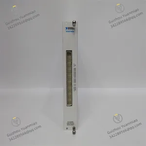
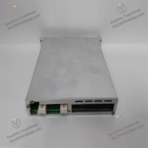
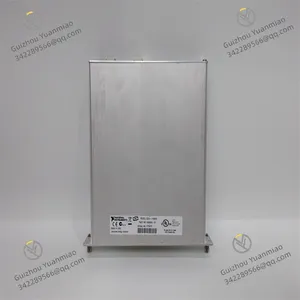
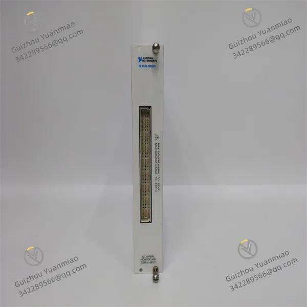
NI SCXI-1162HV Digital I/O Module
Related Products
I. Product Overview
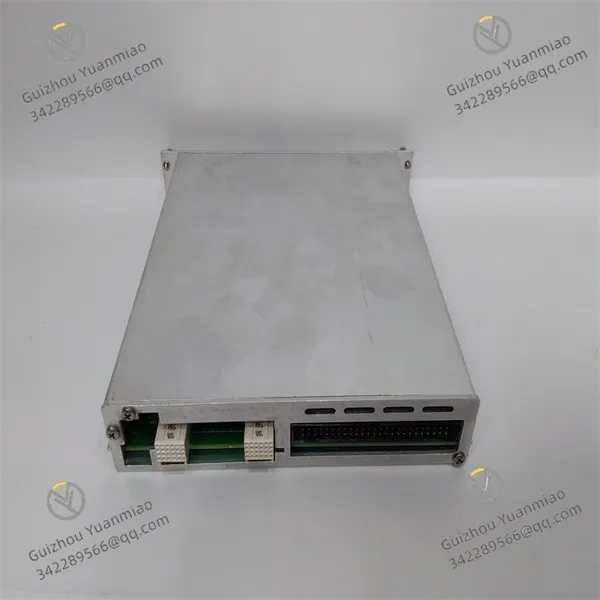
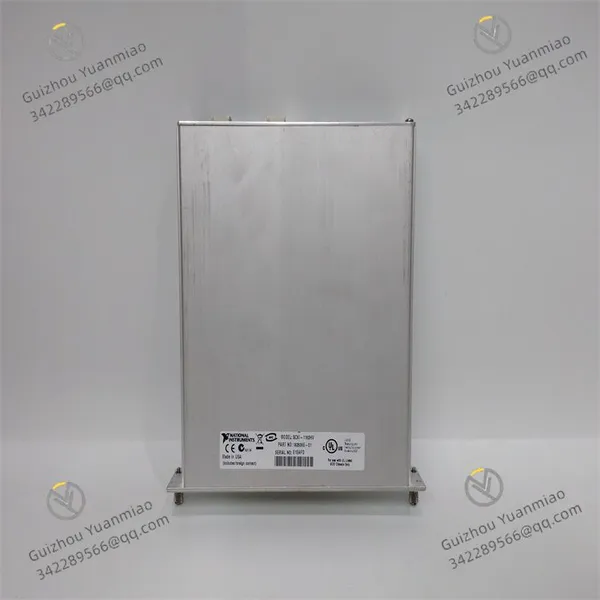
National Instruments SCXI-1162HV (Part Number: 777071-62) is an 8-channel isolated high-voltage analog input module specifically designed for the SCXI signal conditioning system and compatible with chassis such as the SCXI-1001 and SCXI-1000 series. Its core function is to isolate, attenuate, filter, and condition ±600V high-voltage DC or AC signals, converting them into standard low-voltage signals that can be acquired by DAQ devices, thus achieving accurate data acquisition in high-voltage scenarios. Equipped with features including high-voltage isolation, wide-range adaptability, and low-noise conditioning, this module seamlessly integrates with development environments such as LabVIEW and Python via the NI-DAQmx driver software. It is widely used in high-voltage signal acquisition fields including industrial high-voltage equipment monitoring, power system testing, new energy battery detection, and industrial process control.
Adopting a 6U standard SCXI module size and supporting independent configuration of 8 channels, the module provides a safe and reliable solution for high-voltage signal acquisition with 2500Vrms inter-channel isolation, 16-bit ADC resolution, and industrial-grade stability. It ensures the safety of operators and equipment while guaranteeing the accuracy and integrity of acquired data.

II. Functional Features
8-Channel High-Voltage Isolation and Wide-Range Adaptability
High-Precision and Low-Noise Acquisition Performance
Flexible Expansion and System Integration Capability
Safety Protection and Reliable Design
Full-Scenario Adaptability and Core Functions
III. Technical Parameters
IV. Working Principle
V. Operation Guide
1. Installation StepsInstallation Environment
Install in the standard slot of the SCXI series chassis, away from strong electromagnetic interference sources (e.g., high-voltage cables, frequency converters), high-temperature heat sources, and humid environments. Reserve ≥10cm heat dissipation space around the chassis to avoid the ambient temperature exceeding the range of -20℃~+65℃.
Mechanical Installation
Wiring Specifications
2. Configuration and Debugging
Software Installation and Driver Configuration
Channel Parameter Configuration
Power-on Debugging
3. Operation and Maintenance
Status Monitoring
Regular Maintenance
4. Common Fault Troubleshooting

Send Inquiry to This Supplier


You May Also Like
-
NI PCI-6224 GPIB ControllerNegotiableMOQ: 1 Piece
-
NI SCXI-1327 High-Voltage Attenuator Terminal BlockNegotiableMOQ: 1 Piece
-
NI SCXI-1346 ChassisNegotiableMOQ: 1 Piece
-
NI SCXI-1126 8-Channel Frequency Input ModuleNegotiableMOQ: 1 Piece
-
NI BNC-2110 Series Shielded Connector BlocksNegotiableMOQ: 1 Piece
-
NI GPIB-140A GPIB Interface DeviceNegotiableMOQ: 1 Piece
-
NI-9505 Series Motor Drive ModuleNegotiableMOQ: 1 Piece
-
NI-9853 Controller Area Network (CAN) InterfaceNegotiableMOQ: 1 Piece
-
NI CFP-AI-100 Current Analog Input ModuleNegotiableMOQ: 1 Piece
-
NI CFP-AO-210 8-Channel Voltage Output ModuleNegotiableMOQ: 1 Piece


