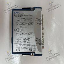
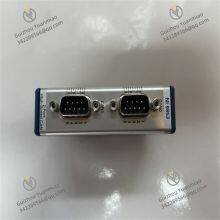
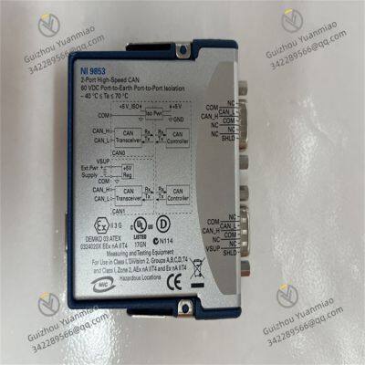
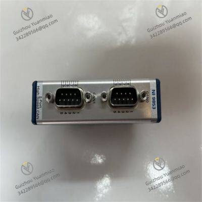
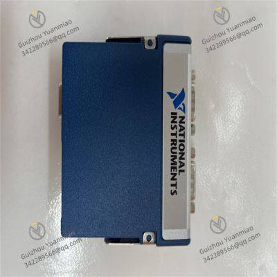
Home > Electrical & Electronics > Electrical Control System > NI-9853 Controller Area Network (CAN) Interface

NI-9853 Controller Area Network (CAN) Interface

NI-9853 Controller Area Network (CAN) Interface photo-1
NI-9853 Controller Area Network (CAN) Interface photo-2
NI-9853 Controller Area Network (CAN) Interface photo-3
Negotiable MOQ: 1 Piece (Price negotiable depending on order volume and customization)
Key Specifications
Get Latest Price
Material:
Other, Global universal model
Condition:
Other, Global universal model
Task:
Other, Global universal model
Payment & Shipping
Payment Methods:
Port of Shipment:
China
Delivery Detail:
Delivery time depends on order quantity.
Material Other, Global universal model
Condition Other, Global universal model
Task Other, Global universal model
Mathematical Model Other, Global universal model
Signal Other, Global universal model
Customized Non-Customized
Structure Other, Global universal model
Operating temperature -40°C to 70°C
Storage temperature -40°C to 85°C
Weight 150g
NI-9853Functional Features
  • Dual High-Speed CAN Ports: Equipped with two 9-pin male DSUB connectors for CAN bus connection. Two high-speed CAN ports meet diverse CAN communication requirements.

  • Dual Power Supply Modes:

    • CAN0 port is internally powered by the module, requiring no external power supply.

    • CAN1 port is powered by an external 8–25VDC supply, and the CAN bus is powered via the VSUP pin of the CAN1 port.

  • Multi-Environment Adaptability: Suitable for hazardous environments (Class I, Division 2, Groups A, B, C, D, T4; Class I, Zone 2, AEx nA IIC T4, Ex nA IIC T4) and non-hazardous environments.

  • High Signal Integrity:

    • CAN_H and CAN_L pins of each port connect to CAN bus signals. Twisted-pair cables are recommended to enhance signal integrity.

    • Each port includes an optional shield pin (SHLD). Connecting this pin in noisy environments further improves signal integrity and EMC performance.

Technical Parameters
  • Communication Parameters:
    • Number of ports: 2

    • Physical layer: High-speed

    • Maximum baud rate: 1 Mbps

    • Supported protocols: 11-bit and 29-bit arbitration ID support; compatible with J1939 networks.

  • Electrical Parameters:
    • Power consumption: Up to 625 mW in transmit mode; up to 400 mW in receive mode.

    • Maximum port-to-COM voltage: -27 to +40VDC (Measurement Category I).

  • Mechanical Parameters:
    • Weight: 150g.

  • Temperature Parameters:
    • Operating temperature: -40°C to 70°C.

    • Storage temperature: -40°C to 85°C.

NI-9853 (3)

NI-9853 (2)

NI-9853 (1)

Common Faults and SolutionsI. Hardware Connection and Power Failures
  1. Module Unpowered or Indicator Off
    • Possible causes:

      • Power input not connected or voltage out of range (18–30VDC required).

      • Damaged power cable or poor interface contact.

      • Internal power circuit failure.

    • Solutions:

      • Check the output voltage of the power adapter with a multimeter to ensure it is within 18–30V.

      • Replace the power cable or re-plug the power interface to ensure good contact.

      • If the power supply is normal but the module still does not respond, contact NI technical support for hardware inspection

  2. Overvoltage/Overcurrent Protection Triggered
    • Possible causes:

      • Input voltage exceeds 30VDC, or motor load is too high, causing current to exceed the rated value (5A continuous, 10A peak).

      • Motor or cable short circuit.

    • Solutions:

      • Disconnect the power supply, check if the input voltage is stable, and eliminate power fluctuation issues.

      • Measure the motor winding resistance with a multimeter to confirm short circuit; replace the motor or repair the cable if shorted.

      • Reset protection parameters in NI MAX or LabVIEW and restart the module.

II. Communication and Interface Failures
  1. Communication Failure with Host Computer (LabVIEW/FPGA)
    • Possible causes:

      • Poor contact or damage to communication cables (e.g., USB, EtherCAT).

      • Incorrect installation or incompatible version of module driver.

      • Misconfigured communication parameters (baud rate, protocol).

    • Solutions:

      • Replace the communication cable and ensure the interface is secure; confirm if the module is recognized in NI MAX.

      • Uninstall and reinstall the latest NI drivers (e.g., NI-DAQmx, LabVIEW FPGA Module).

      • Check the communication parameter settings of the module in the project explorer to ensure consistency with the host computer (e.g., CANopen baud rate must match).

  2. Abnormal Industrial Bus (e.g., CANopen, EtherCAT) Communication
    • Possible causes:

      • Bus termination resistors not connected (CANopen requires 120Ω resistors at both ends).

      • Excessively long bus cables or non-standard cabling causing signal interference.

      • Slave address conflicts or protocol configuration errors.

    • Solutions:

      • Check if bus termination resistors are correctly connected and use an oscilloscope to view stable bus waveforms.

      • Shorten the bus length, use shielded cables, and ground them to reduce electromagnetic interference.

      • Check slave addresses in configuration tools (e.g., CANopen configuration software) to ensure uniqueness; re-initialize the bus protocol.

III. Motor Control Function Failures
  1. Motor Not Rotating or Rotating Abnormally
    • Possible causes:

      • Incorrect control mode setting (e.g., target value not input in position mode).

      • Abnormal encoder feedback leading to closed-loop control failure.

      • Incorrect motor wiring (phase sequence error, ground not connected) or driver output failure.

    • Solutions:

      • Confirm the control mode (position/speed/torque) and command input in LabVIEW, and try manually sending control signals (e.g., jog mode).

      • Check encoder cable connections and use an oscilloscope to measure encoder pulses; replace the encoder or cable if pulses are missing.

      • Reconnect cables according to the motor wiring diagram to ensure correct phase sequence; test whether the driver output port has voltage in NI MAX.

  2. Positioning Accuracy Deviation or Jitter
    • Possible causes:

      • Unoptimized three-loop control parameters (PID) leading to system oscillation.

      • Uneven mechanical load or excessive transmission system clearance.

      • Insufficient encoder resolution or loose installation.

    • Solutions:

      • Use LabVIEW's PID tuning tool to gradually adjust proportional (P), integral (I), and derivative (D) parameters to suppress jitter (e.g., decrease P value, increase D value).

      • Inspect the mechanical structure, tighten components like couplings and guides to reduce clearance; add load balancing measures if necessary.

      • Confirm whether the encoder resolution meets requirements (e.g., incremental up to 20 MHz) and re-fix the encoder installation position.

Product Tags: NI-9853

Send Inquiry to This Supplier

Message
0/5000
Want the best price? Post an RFQ now!
1Yr
Business Type
Trading Company
Year Established
2014
Factory Size
1,000-3,000 square meters
Product Certifications
SA8000