Material
Other, Global universal model
Condition
Other, Global universal model
Task
Other, Global universal model
Mathematical Model
Other, Global universal model
Signal
Other, Global universal model
Customized
Non-Customized
Structure
Other, Global universal model
Operating Temperature
0℃~+60℃
Relative Humidity
5%-95% (non-condensing)
Dimensions
160×100×233mm
I. Product Overview
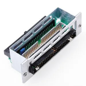
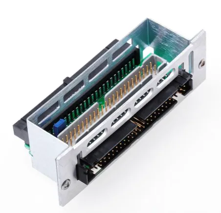
National Instruments SCXI-1349 is a 68-pin high-density shielded terminal block module with the part number 777932-01. Specifically designed for the NI SCXI signal conditioning system, it serves as an intermediate adapter between SCXI modules (such as SCXI-1125, SCXI-1127, SCXI-1132, etc.) and external sensors, actuators, or data acquisition devices. Its core functions include organizing the wiring and ensuring stable transmission of 68-channel signals, supporting high-precision conversion of analog, digital, and sensor signals (voltage and current types). Meanwhile, it features shielding and anti-interference, convenient wiring, and reliable protection.
Adopting a 3U standard rack-mount design, this product is compatible with SCXI chassis (such as SCXI-1000, SCXI-1001). It directly connects to SCXI signal conditioning modules via a 68-pin VHDCI interface and is equipped with 68 independent screw-locking terminals for quick connection to external sensors, actuators, or other signal sources. Widely used in scenarios like industrial automation data acquisition, laboratory scientific research testing, and electronic equipment detection, it is a key adapter component for external signal access in the NI SCXI signal conditioning system. It can effectively organize wiring, suppress interference, ensure signal transmission integrity, and improve system construction and maintenance efficiency.
II. Functional Features
68-Pin Full-Channel Signal Adaptation and Organized Wiring
Equipped with 68 independent screw-locking terminals corresponding to the 68 signal channels of SCXI modules, it supports full-type signal conversion of Analog Input (AI), Analog Output (AO), Digital Input (DI), Digital Output (DO), and sensor signals (voltage and current types), enabling two-way signal interaction between external devices and SCXI modules.
Terminal definitions strictly comply with the standard signal allocation rules of the NI SCXI system, with a one-to-one correspondence to the pins of SCXI modules (e.g., AI0 corresponds to Terminal 1, AGND corresponds to Terminal 34). Clear markings (channel number, signal type) are etched on the terminal surface, facilitating quick wiring, line checking, and troubleshooting, and avoiding data distortion or equipment damage caused by incorrect signal connection.
It supports a wide range of signal adaptation, and can directly connect low-level sensor signals (μV level), standard industrial signals (0–10V, 4–20mA), and digital signals (5V TTL/CMOS) without additional adapter components. It meets the requirements of data acquisition and control with different precisions, and is suitable for various sensors such as pressure, temperature, and displacement sensors, as well as actuators such as relays and cylinders.
Strong Anti-Interference Shielding Design and Signal Integrity Assurance
The module adopts an all-metal shielded enclosure, and the internal signal channels are arranged in twisted pairs with a shielding coverage rate ≥ 95%. It can effectively suppress Electromagnetic Interference (EMI) and Radio Frequency Interference (RFI), reduce the impact of external interference on signals in industrial field or laboratory environments, and is especially suitable for low-level signal transmission in strong electromagnetic environments.
The wiring terminals adopt a gold-plated contact design, which is oxidation-resistant and corrosion-resistant, with a contact resistance ≤ 5mΩ and a plug-in life ≥ 1000 times. It can maintain stable contact performance during long-term use, avoiding signal interruption or fluctuation caused by contact oxidation; the screw-locking terminals are suitable for 14–22AWG wires, ensuring firm wiring and preventing loosening due to vibration.
Built-in grounding busbar supports the separated design of Signal Ground (SGND) and Protective Ground (PGND), which can effectively isolate ground loop interference. The insulation resistance between terminals is ≥ 100MΩ @ 500VDC, and the leakage current is ≤ 1μA, ensuring the stability and safety of signal transmission.
Reliable Structure and Safety Protection
Adopting a 3U standard rack-mount design, it is compatible with all NI SCXI chassis installation slots. It is locked to the chassis through a snap-fit structure, featuring stable installation and strong vibration resistance (vibration tolerance: 5g, 10Hz–500Hz), and is suitable for different installation environments in industrial fields and laboratories.
The wiring terminals have anti-misinsertion and short-circuit protection designs, with a reasonable terminal spacing (≥ 2.54mm) to avoid short-circuit risks caused by exposed wire cores; the module enclosure has an electrostatic protection function (±2kV contact discharge), effectively protecting the internal circuit and SCXI modules from electrostatic damage.
It supports a rated voltage of 30V DC/AC and a rated current of 1A per terminal, meeting the electrical safety requirements of industrial signal transmission. It has overcurrent and overvoltage protection capabilities (in conjunction with the protection functions of SCXI modules), avoiding module damage caused by the access of over-range signals.
Flexible Adaptation and Convenient Use
Fully compatible with the full range of NI 68-pin SCXI signal conditioning modules (such as SCXI-1125, SCXI-1127, SCXI-1132, SCXI-1167, etc.), it requires no additional drivers or configurations and is plug-and-play. It directly connects to SCXI modules via a 68-pin VHDCI cable, simplifying the system construction process.
The front of the module is equipped with a transparent dust cover, which can be closed after wiring is completed, effectively preventing dust and debris from entering the terminal area and reducing the risk of faults; the cover has a reserved marking area where wiring diagrams can be pasted for easy later maintenance and line checking.
Supports multi-module stacking expansion. Multiple SCXI-1349 modules can be installed in the same SCXI chassis, and combined with multi-channel SCXI modules to build large-scale signal acquisition and control systems, suitable for complex industrial automation or scientific research testing scenarios.
Full-Scenario Adaptation and Core Functions
Core functions include: signal conversion between SCXI modules and external devices, wiring organization and management, interference suppression and signal protection, and system maintenance facilitation. It is a key bridge connecting external signal sources and conditioning modules in the NI SCXI signal conditioning system.
Suitable for multi-field applications: industrial automation production line data acquisition, power equipment condition monitoring, automotive electronics testing, aerospace scientific research experiments, laboratory multi-channel signal acquisition and other scenarios, especially suitable for high-precision signal conditioning needs that require organized wiring and interference suppression.

III. Technical Specifications
IV. Working Principle
The core working logic of the NI SCXI-1349 is "Signal Access → Organized Conversion → Shielded Transmission → Stable Output", with the specific process as follows:
Signal Access: Signals from external sensors, actuators, or signal sources are connected to the corresponding terminals of the SCXI-1349 via wires. Matching terminal channels are selected according to signal types (analog, digital, sensor signals), e.g., 4–20mA current signals are connected to AI channel terminals, and digital control signals are connected to DO channel terminals.
Organized Conversion: The module internally realizes one-to-one correspondence between 68 terminals and 68-pin VHDCI interface pins through standardized wiring, achieving organized signal conversion and avoiding wiring confusion; the built-in grounding busbar centrally connects the signal ground of each channel to reduce ground loop interference.
Shielded Transmission: The metal shielded enclosure and internal twisted-pair layout work together to isolate external electromagnetic interference, ensuring that signals are transmitted without distortion or interference inside the module; gold-plated terminals and screw-locking structures ensure good signal contact and reduce transmission loss.
Stable Output: Signals processed through organization and shielding are transmitted to the SCXI signal conditioning module via a 68-pin VHDCI cable. The SCXI module completes signal conditioning functions such as amplification, filtering, and isolation, and then transmits the signals to the DAQ device for data acquisition or control command execution, forming a complete closed-loop signal link.
V. Operation Guide
1. Installation StepsInstallation Environment
Install in an idle slot of the SCXI chassis, place in a dry and well-ventilated environment, away from strong electromagnetic interference sources (such as frequency converters, high-voltage cables), high-temperature heat sources (such as power modules), and humid areas; the chassis must be well-grounded (ground resistance ≤ 4Ω) to ensure the system's anti-interference capability and safety.
Mechanical Installation
Turn off the power of the SCXI chassis, align the SCXI-1349 module with the chassis slot guide rail, push it in smoothly until the snap locks, ensuring that the module is in good contact with the chassis backplane interface; after installation, gently pull the module to confirm it is not loose, and observe the module panel indicator (off when not powered on).
If multiple modules are installed, arrange them in the order of "left to right", reserve a heat dissipation space of ≥ 5cm between modules to avoid poor heat dissipation caused by stacking; tighten the chassis fixing screws to enhance the module's vibration resistance.
Module Connection
Use a 68-pin VHDCI cable (such as NI SH68M-68F-EPM) to connect the VHDCI interface of the SCXI-1349 to the corresponding interface of the SCXI signal conditioning module, insert along the positioning slot and lock the snap to ensure a firm connection;
Connect external devices: according to the signal type and terminal definition, connect the wires of sensors and actuators to the corresponding wiring terminals, tighten the screws (torque ≤ 0.5N·m), ensuring that the wire cores are not exposed to avoid short circuits.
2. Wiring Specifications
Pre-Wiring Preparation
Refer to the pin definition manuals of the SCXI module and SCXI-1349 to clarify the correspondence between terminals and SCXI module channels (e.g., AI0 corresponds to Terminal 1, AO0 corresponds to Terminal 35, DI0 corresponds to Terminal 50), draw a wiring diagram to avoid incorrect connection.
Cut 14–22AWG wires, strip about 5mm of insulation from both ends to ensure the wire cores are free of oxidation and breakage; stranded wires need to be crimped with cold-pressed terminals, and solid wires can be directly connected to the terminals.
Wiring Operation
Analog Signal Wiring: The positive terminal of single-ended input signals is connected to the AIx terminal, and the negative terminal to the AGND terminal; the positive terminal of differential input signals is connected to AIx+, and the negative terminal to AIx-, with the signal ground connected to the AGND terminal.
Sensor Signal Wiring: The 4–20mA current signal is connected to the AI channel terminal in series to ensure correct power polarity (the positive terminal is connected to the signal source output, and the negative terminal to the module terminal); the 0–10V voltage signal is directly connected to the AI terminal and AGND terminal to avoid overload input.
Digital Signal Wiring: DI signals are output from external devices and connected to DI terminals; DO signals are led from DO terminals to external actuators to ensure the signal level matches (5V TTL/CMOS). A current-limiting resistor must be connected in series with the actuator if the current exceeds 1A.
Grounding and Anti-Interference
Connect the Protective Ground (PGND) terminal of the module to the system ground bar with a ground resistance ≤ 4Ω; short-circuit the Signal Ground (SGND) and AGND terminals to form a unified signal ground, avoiding interference caused by ground potential differences.
Route analog signal cables and digital signal cables separately with a spacing ≥ 30cm; use shielded cables for long-distance transmission, with the shield layer grounded at one end (connected to the system ground) to enhance anti-interference capability.
3. Operation and Maintenance
Status Monitoring
Monitor the signal status through SCXI system software (such as NI MAX) or DAQ device software:
Normal Status: The collected signal is stable without noise fluctuation, the module enclosure temperature ≤ 40℃, the terminals have no heating, and there is no alarm information;
Fault Status: Signal distortion, packet loss, or the SCXI module reports an error of "signal abnormality", and the machine must be shut down for inspection immediately.
Regular Maintenance
Monthly: Clean dust on the module surface and terminal area with dry compressed air, check whether the wiring terminals are loose or oxidized, re-tighten loose terminals, and wipe oxidized contacts with alcohol pads.
Semi-Annually: Test the terminal contact resistance (measured with a multimeter, ≤ 5mΩ); check whether the shielded enclosure is reliably grounded; verify the insulation resistance (≥ 100MΩ between terminals), and replace aging wires.
Annually: Perform a comprehensive cleaning of the module, check whether the internal wiring is aging or loose; back up the wiring diagram and system configuration to facilitate quick recovery after faults.
4. Common Troubleshooting