Material
Other, Global universal model
Condition
Other, Global universal model
Task
Other, Global universal model
Mathematical Model
Other, Global universal model
Signal
Other, Global universal model
Customized
Non-Customized
Structure
Other, Global universal model
Operating Temperature
0℃ to 60℃
Relative Humidity
5%-95% (non-condensing)
Dimensions
160×100×233 mm
I. Product Overview
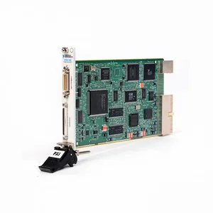
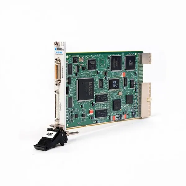
National Instruments PXI-7340 (Part Number: 185119C-01) is a 4-axis independent/coordinated motion controller designed based on the PXI bus architecture and compatible with PXI 3U specification chassis. Its core functions include precise position control, speed control, torque control, and trajectory planning for 4-axis stepper motors or servo motors, supporting complex motion modes such as point-to-point motion, linear interpolation, and circular interpolation.
Equipped with features like high sampling rate, low latency, and multi-axis synchronization, the controller seamlessly integrates with development environments such as LabVIEW and C/C++ via the NI-Motion driver software. It is widely used in scenarios including automated test equipment, precision machine tools, electronic manufacturing equipment, and robotic systems, providing a stable and reliable solution for high-demand motion control tasks.
Adopting a 3U PXI standard module size, the controller integrates a high-performance DSP processor and FPGA chip, with independent axis control channels and rich I/O interfaces. It supports the connection of various feedback devices (encoders, linear scales) and can achieve nanometer-level precision motion control, meeting the stringent requirements of precision manufacturing and high-end testing fields.
II. Functional Features
4-Axis High-Precision Motion Control and Trajectory Planning
Supports 4-axis independent control or multi-axis coordinated control. Each axis is equipped with a 32-bit position counter (resolution up to 1 nm), a 32-bit speed controller (range: 0.1 μm/s ~ 1 m/s), and a 16-bit torque controller, compatible with stepper motors (maximum pulse output frequency: 2 MHz) and servo motors (supporting analog command output of ±10 V).
Built-in rich trajectory planning algorithms, supporting point-to-point motion (PT), linear interpolation (2–4 axes), circular interpolation (2 axes), helical interpolation (3 axes), and spline curve interpolation, with interpolation accuracy ≤ ±1 LSB. It meets the requirements of complex path motion scenarios (e.g., electronic component placement, precision cutting).
The position loop update rate reaches 1 kHz, and the speed loop update rate reaches 10 kHz. The trajectory look-ahead function supports pre-planning of up to 1,000 motion segments, effectively reducing motion start-stop shocks, realizing smooth and high-speed trajectory transitions, and improving motion control stability.
Multi-Feedback Modes and Closed-Loop Control Capability
Each axis supports the connection of feedback devices such as incremental encoders (maximum sampling rate: 5 MHz), absolute encoders (SSI, BiSS-C protocols), and linear scales, enabling multi-loop closed-loop control of position feedback, speed feedback, and torque feedback, with positioning accuracy ≤ ±0.1 μm (depending on feedback device accuracy).
Integrates an adaptive PID control algorithm, supporting real-time adjustment of proportional gain (P), integral gain (I), and derivative gain (D). It is equipped with feedforward compensation and friction compensation functions, effectively suppressing load disturbances and system lag, and improving dynamic response performance (step response time ≤ 10 ms).
Supports position error monitoring and alarm functions. The position error threshold can be set; when the deviation between the actual position and the command position exceeds the threshold, an alarm is automatically triggered and preset protection actions (e.g., emergency stop, deceleration) are executed to ensure equipment safety.
Rich I/O Interfaces and Expansion Capability
Equipped with 32-channel general-purpose digital I/O interfaces (16 inputs/16 outputs), supporting 5 V TTL/CMOS levels. They can be configured as limit switch inputs, home signal inputs, emergency stop signal inputs, cylinder control outputs, etc., meeting the signal interaction requirements in motion control.
Each axis is provided with dedicated limit signal interfaces (positive limit, negative limit), home signal interface, and emergency stop signal interface, supporting dual protection of hardware emergency stop and software emergency stop with a response time ≤ 1 ms to ensure the safety of the motion process.
Supports linkage with PXI data acquisition modules and PXI signal generation modules via the PXI bus, realizing synchronous triggering of motion control, data acquisition, and signal excitation (synchronization accuracy ≤ 10 μs), suitable for collaborative work scenarios in automated test systems.
Flexible System Integration and Programming Support
Compatible with all PXI 3U specification chassis (e.g., NI PXI-1042, PXIe-1082), supporting multi-module stacking to expand the number of axes (up to 16 axes in total). It can be combined with NI PXI series I/O modules and communication modules to build complex motion control systems.
Supports NI-Motion driver software and is compatible with development environments such as LabVIEW, LabWindows/CVI, C/C++, and Python. It provides a graphical programming function library and textual API interfaces, enabling motion mode configuration, parameter adjustment, status monitoring, and data recording through software, simplifying the system development process.
Supports the import of custom motion trajectories (e.g., CSV format trajectory files) and has a trajectory simulation function, which can verify the rationality of the trajectory before actual motion and reduce debugging risks. It supports real-time storage of motion data (position, speed, torque data) with a sampling rate of up to 1 kHz, facilitating post-analysis and optimization.
Industrial-Grade Reliable Design and Full-Scenario Adaptation
Features an industrial-grade operating temperature range (0℃~+60℃), with multiple protection functions such as overvoltage protection (±15 V power input), overcurrent protection (maximum I/O interface current: 50 mA), and electrostatic discharge protection (±2 kV contact discharge), adapting to various environments such as industrial sites and laboratories.
Core functions cover: precision position control, multi-axis synchronous linkage, complex trajectory planning, and collaboration between motion control and data acquisition. It is suitable for multi-field applications: electronic manufacturing (chip packaging, PCB drilling), precision machining (micro-component cutting), automated testing (sensor calibration, equipment verification), and robotic systems (collaborative robots, Cartesian robots).

III. Technical Specifications
IV. Working Principle
The core working logic of the NI PXI-7340 follows the sequence of "Command Input → Trajectory Planning → Drive Output → Feedback Adjustment → Status Monitoring", with the specific process as follows:
Command Input: Motion commands (including motion mode such as linear interpolation, target position, speed, acceleration, etc.) are input via host computer software (e.g., LabVIEW) and transmitted to the DSP processor inside the controller through the PXI bus.
Trajectory Planning: Based on the input commands, the DSP processor calls the built-in trajectory planning algorithm (e.g., S-curve acceleration/deceleration algorithm) to generate a smooth position-time trajectory curve. Meanwhile, it optimizes trajectory transitions through the look-ahead function to avoid motion shocks.
Drive Output: Trajectory commands are converted into motor drive signals by the FPGA chip. In stepper motor mode, pulse/direction signals are output (maximum frequency: 2 MHz); in servo motor mode, ±10 V analog speed/torque commands are output to drive the motor to perform motion.
Feedback Adjustment: Feedback devices (e.g., encoders) collect the actual position and speed signals of the motor in real time and transmit them to the position loop and speed loop controllers of the controller. These signals are compared with the command signals, and the drive output is adjusted through the adaptive PID algorithm to achieve closed-loop control, compensating for position errors and speed fluctuations.
Status Monitoring: The controller monitors the motor operating status (position error, speed, current) and I/O signals (limit, emergency stop) in real time. When an abnormality is detected (e.g., position error exceeding the limit, emergency stop trigger), an alarm is immediately triggered and protection actions (e.g., stopping drive output) are executed. Meanwhile, status information is fed back to the host computer to facilitate troubleshooting.
V. Operation Guide
1. Installation StepsInstallation Environment
Install the controller in an idle slot of a PXI 3U specification chassis, away from strong electromagnetic interference sources (e.g., frequency converters, high-voltage cables), high-temperature heat sources (e.g., power modules), and humid areas. The chassis must be well-grounded (ground resistance ≤ 4 Ω) to ensure stable bus communication and equipment safety.
Mechanical Installation
Turn off the power supply of the PXI chassis. Align the controller with the chassis slot guide rail and push it in smoothly until the buckle locks, ensuring the controller is in good contact with the chassis backplane bus and power interface. After installation, gently pull the controller to confirm it is not loose.
Check whether the indicators (power light, ready light) on the controller panel are normal (both off when not powered on). Confirm that the I/O interfaces and feedback interfaces are free of dust and oxidation to ensure reliable subsequent wiring.
Module Connection
Motor Connection: Connect stepper motors to the "STEP" and "DIR" pins of the controller via pulse/direction interfaces; connect servo motors to the servo driver via the analog command interface ("AO" pin), and connect the enable signal ("EN" pin) of the servo driver at the same time.
Feedback Device Connection: Connect the A/B/Z phase signals of the encoder to the "ENC A", "ENC B", and "ENC Z" pins of the corresponding axis of the controller respectively, ensuring correct wiring polarity (reversing A/B phases will cause position counting errors).
I/O Signal Connection: Connect limit switches and home switches to dedicated limit/home interfaces; connect the emergency stop button to the "EMERGENCY STOP" interface. Connect other control signals (e.g., cylinder control) to general-purpose digital I/O interfaces. Use shielded cables for wiring, with the shield layer grounded at one end.
2. Configuration and Debugging
Software Installation and Driver Configuration
Install the NI-Motion driver software (compatible with Windows 10/11, LabVIEW 2018 and above versions). Restart the computer and open the NI Measurement & Automation Explorer (MAX) software.
Expand "Devices and Interfaces" in MAX, right-click the PXI chassis and select "Refresh". MAX will automatically identify the NI PXI-7340 controller. Right-click the controller and select "Properties" to configure parameters such as bus address and trigger mode, then click "Apply" to save the settings.
Motion Parameter Configuration
Open the LabVIEW software and create a new project. Call the "Motion Initialize" function in the NI-Motion function library to initialize the controller, selecting the number of control axes and motor type (stepper/servo).
Use the "Motion Configure Axis" function to configure parameters for each axis: position resolution, maximum speed, acceleration, PID gain, feedback device type, etc. Set the trajectory mode (e.g., linear interpolation) and interpolation parameters via the "Motion Configure Trajectory" function.
Power-On Debugging
Start the devices in the order of "PXI chassis → host computer". Observe the power light (steady green) and ready light (steady green) on the controller panel; normal indicator status indicates the controller is operating properly.
Single-Axis Point-to-Point Motion Test: Configure the single-axis target position (e.g., 10 mm) and speed (100 mm/s), call the "Motion Start" function to start the motion, and read the actual position via the "Motion Read Position" function. Compare the command position with the actual position; the deviation should be ≤ ±0.1 μm to verify positioning accuracy.
Multi-Axis Interpolation Test: Configure a 2-axis linear interpolation trajectory (e.g., 10 mm for X-axis, 5 mm for Y-axis). After starting the motion, observe whether the motor motion trajectory is smooth without stuttering or deviation; normal interpolation function is indicated if no such issues occur.
Emergency Stop and Limit Test: Trigger the emergency stop button or limit switch; the controller should immediately stop the motion output, and the host computer displays alarm information, verifying that the protection function is normal.
3. Operation and Maintenance
Status Monitoring
Monitor the status in real time via MAX or host computer software:
Normal Status: Controller indicators are steady green, the motor runs smoothly, position error ≤ ±0.1 μm, no alarm information, and controller temperature ≤ 60℃.
Fault Status: The red light is on (power failure), the yellow light flashes (alarm), and the host computer displays information such as position error exceeding the limit and feedback signal loss. The system must be shut down immediately for inspection.
Regular Maintenance
Monthly: Clean dust from the controller panel interfaces with dry compressed air, check whether the wiring of motors and feedback devices is loose or oxidized, and tighten loose components. Calibrate feedback devices via MAX software to ensure positioning accuracy.
Semi-Annual: Check whether the controller supply voltage (+5 V, ±15 V) is stable with a fluctuation range ≤ ±5%. Test the signal integrity of I/O interfaces and measure the output signal level with a multimeter to ensure it meets requirements.
Annual: Perform a comprehensive cleaning of the controller, check whether the internal cooling fan (if any) is operating normally, and clean dust from the heat dissipation channel. Re-calibrate axis parameters and PID gains via the NI-Motion calibration tool to optimize control performance. Back up system configuration parameters and motion programs to facilitate quick recovery after faults.
4. Common Troubleshooting