Home > Electrical & Electronics > Electrical Control System > NI SCXI-1304 Terminal Block

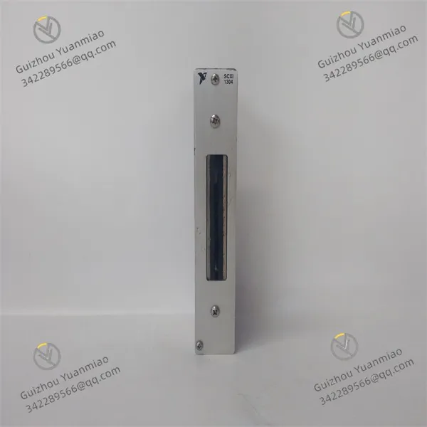
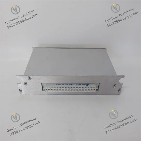
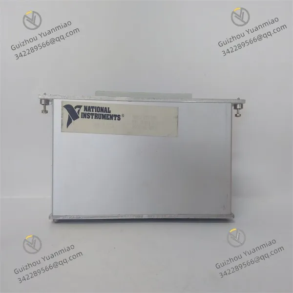
NI SCXI-1304 Terminal Block

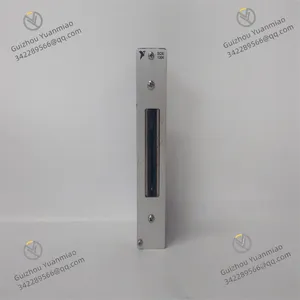
NI SCXI-1304 Terminal Block photo-1
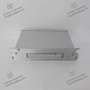
NI SCXI-1304 Terminal Block photo-2
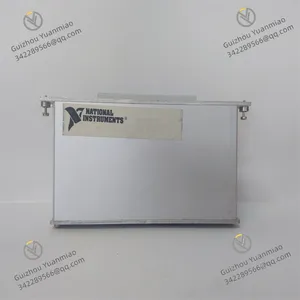
NI SCXI-1304 Terminal Block photo-3
Negotiable MOQ: 1 Piece (Price negotiable depending on order volume and customization)
Key Specifications
Get Latest Price
Material:
Other, Global universal model
Condition:
Other, Global universal model
Task:
Other, Global universal model
Payment & Shipping
Payment Methods:
Port of Shipment:
guizhou
Delivery Detail:
Delivery time depends on order quantity.
Material Other, Global universal model
Condition Other, Global universal model
Task Other, Global universal model
Mathematical Model Other, Global universal model
Signal Other, Global universal model
Customized Non-Customized
Structure Other, Global universal model
Operating Temperature 0℃ to +60℃
Relative Humidity 5%-95% (non-condensing)
Dimensions 2.7×146×190.5mm

I. Product Overview


National Instruments SCXI-1304 (Part Number: 777026-04) is a 48-pin DIN Type C front-mount terminal block, specifically designed for SCXI series analog I/O modules and high-voltage input modules. It is compatible with the 48-pin DIN Type C front connectors of modules such as the SCXI-1162HV, SCXI-1124, and SCXI-1102. Its core function is to convert the on-board signal interfaces of modules into open terminal blocks, enabling safe and reliable connection between external signals and SCXI modules.


Featuring convenient wiring, anti-misinsertion protection, and anti-interference capabilities, this terminal block supports stable transmission of high-voltage signals and analog signals. It is widely used in scenarios such as industrial high-voltage equipment testing, power system signal acquisition, and laboratory research experiments, serving as a key adapter component for connecting external signals to modules in SCXI signal conditioning systems.


With a wall-mount or desktop-mount design, the terminal block is equipped with 48 independent screw-locking terminals. These terminals ensure secure wiring with low contact resistance, effectively guaranteeing the integrity and stability of signal transmission. Meanwhile, they simplify module wiring and maintenance procedures, reducing operational complexity.


SCXI-1304 (2)


II. Functional Features


48-Pin Full Compatibility and Signal Adaptation

  • Equipped with a 48-pin DIN Type C female connector, it is fully compatible with 48-pin front-mount SCXI series modules (e.g., SCXI-1162HV high-voltage module, SCXI-1124 analog output module). It enables full pinout of module signal interfaces, supporting synchronous transmission of analog input/output, digital signals, and power signals.

  • The 48 terminals are arranged in the order of module pin definitions, corresponding to pins such as AI+, AI-, AGND, and power supply on the modules. Each terminal is clearly marked with etched pin numbers, facilitating quick identification during wiring and preventing equipment damage or signal distortion caused by incorrect connections.

  • It supports stable transmission of high-voltage signals (up to 600V DC/AC) and low-level analog signals (μV range). The terminal spacing is designed to be ≥5mm, meeting high-voltage insulation requirements and eliminating the risk of creepage or short circuits in high-voltage signal transmission.


Reliable Wiring and Safety Protection

  • The screw-locking terminal design is compatible with 14–22 AWG wires. After wiring, the terminals are secured with screws, ensuring a contact resistance ≤10mΩ. This effectively prevents wiring loosening due to vibration or pulling, guaranteeing long-term operational reliability.

  • The terminal block housing is made of flame-retardant ABS material, offering excellent insulation performance and mechanical strength. With an IP20 protection rating, it effectively prevents dust and foreign objects from entering the interior, making it suitable for various environments such as industrial sites and laboratories.

  • Incorporates anti-misinsertion design: The connector adopts a DIN Type C foolproof structure, which can only be correctly mated with the matching front connector of SCXI modules, avoiding pin damage caused by reverse insertion or mismatching. A grounding terminal is provided on the side of the terminal block, which can be connected to the system ground bar to reduce the impact of electromagnetic interference.


Anti-Interference and Signal Transmission Optimization

  • Internal wiring features a shielded design. Key signal pins (e.g., analog input pins) are physically separated from power and digital pins to minimize electromagnetic coupling interference. The terminal block housing can be grounded to form a shielding layer, further suppressing the impact of external electromagnetic interference on signal transmission.

  • Terminals are equipped with gold-plated contacts, which are oxidation-resistant and corrosion-resistant, ensuring stable contact performance and low signal transmission loss during long-term use. They are particularly suitable for low-noise, high-precision signal acquisition scenarios (e.g., μV-range analog signal transmission).

  • It supports both stranded and solid wire connections. The internal components of the terminals are made of copper alloy with excellent conductivity, boasting a rated current of 3A. This meets the signal transmission current requirements of SCXI modules without causing overheating or signal attenuation.


Convenient Installation and Maintenance

  • With a compact design, it measures only 12.7×146×190.5mm (0.5×5.7×7.5in) and weighs approximately 0.5kg. Supporting both wall-mount installation (equipped with mounting holes) and desktop placement, it saves installation space and adapts to layout requirements of different scenarios.

  • The terminal block connects to SCXI modules via a snap-on mechanism. For installation, simply align the DIN Type C female connector of the terminal block with the front connector of the module and press the snap to lock it in place. For removal, press the unlock button to separate the terminal block—no tools required for operation.

  • Individual terminals can be detached and replaced (supported by some models). Maintenance does not require disassembling the entire terminal block; only faulty terminals need to be replaced, reducing maintenance costs and downtime. The surface of the terminal block features a dirt-resistant design for easy cleaning.


Full-Scenario Adaptation and Core Functions

  • Core functions include: SCXI module signal interface conversion, safe connection between external signals and modules, anti-interference signal transmission, and simplified wiring maintenance.

  • Suitable for multi-field applications: Signal acquisition wiring for industrial high-voltage equipment (frequency converters, high-voltage motors), test signal connection for power systems (power transmission and transformation equipment), laboratory research experiments (sensor signal access), and wiring for new energy (lithium battery packs, photovoltaic inverters) testing systems.


III. Technical Specifications


Category Specific Parameters
Product Type 48-pin DIN Type C front-mount terminal block (compatible with SCXI modules)
Core Functions Module signal interface conversion, connection between external signals and SCXI modules, anti-interference signal transmission
Connector Configuration Front end: 48-pin DIN Type C female connector (compatible with SCXI 48-pin front-mount modules); Rear end: 48 screw-locking terminals
Compatible Modules SCXI modules with 48-pin DIN Type C front connectors, such as SCXI-1162HV, SCXI-1124, SCXI-1102, SCXI-1104
Wiring Specifications Compatible wires: 14–22 AWG (stranded/solid); Terminal type: Screw-locking; Terminal spacing: 5mm
Transmission Performance Contact resistance ≤10mΩ; Rated current: 3A per terminal; Insulation resistance ≥100MΩ @ 500VDC; Withstand voltage: 1kVAC for 1 minute
Signal Compatibility Supports transmission of high-voltage signals (up to 600V DC/AC), analog signals (μV to V range), and digital signals
Physical Parameters Dimensions: 12.7×146×190.5mm (0.5×5.7×7.5in); Weight: Approximately 0.5kg; Mounting method: Wall-mount/desktop
Environmental Adaptability Operating temperature: 0℃ to +60℃; Storage temperature: -40℃ to +85℃; Humidity: 5%–95% (non-condensing); Housing material: Flame-retardant ABS
Protection Rating IP20 (protects against dust and foreign object intrusion)
Marking and Anti-Misinsertion Terminals with etched pin numbers; Foolproof connector design (DIN Type C anti-misinsertion structure); Housing grounding terminal
Application Scenarios Industrial high-voltage equipment testing wiring, power system signal acquisition, laboratory research experiments, new energy testing systems

SCXI-1304 (3)


IV. Working Principle


The core working logic of the NI SCXI-1304 follows the process of module signal extraction → terminal conversion → external signal access → stable transmission, with specific steps as follows:
  1. Module Signal Extraction: The 48-pin DIN Type C front connector of an SCXI module (e.g., SCXI-1162HV) mates with the DIN Type C female connector of the terminal block. Signal pins of the module, such as AI+, AI-, AGND, and power supply, are routed internally through the terminal block to the corresponding 48 wiring terminals.


  2. Terminal Conversion and Adaptation: The terminal block converts the on-board connector of the module into open screw-locking terminals. Wires from external signal sources (e.g., high-voltage sensors, standard signal generators) are securely connected to the corresponding terminals via screw fastening, achieving physical connection between external signals and module pins.


  3. External Signal Access: Based on application requirements, the positive, negative, and ground terminals of external signals (such as high-voltage signals and analog signals) are connected to the corresponding terminals of the terminal block respectively (e.g., differential signals are connected to AI+ and AI- terminals, and ground is connected to the AGND terminal). During wiring, terminal markings enable quick pin positioning to avoid incorrect connections.


  4. Stable Signal Transmission: The terminal block adopts low-resistance, anti-interference internal wiring design. When the housing is grounded, it forms a shielding layer to suppress external electromagnetic interference. The screw-locking terminals ensure reliable contact between wires and terminals, reducing contact resistance and signal attenuation, thus guaranteeing stable signal transmission from external sources to SCXI modules or from modules to external actuators.


V. Operation Guide


1. Installation StepsInstallation Environment


Place the terminal block in a dry, well-ventilated area, away from strong electromagnetic interference sources (e.g., high-voltage cables, frequency converters), high-temperature heat sources (e.g., heaters), and humid environments. Select an installation location convenient for wiring and maintenance. It is recommended that the distance from the SCXI module be ≤1 meter to minimize signal transmission distance and interference.


Mechanical Installation

  • Desktop Installation: Place the terminal block stably on a horizontal desktop, ensuring the wiring terminals face the operation side for easy wire access.

  • Wall-Mount Installation: Use M4 screws to fix the mounting holes of the terminal block to a wall or equipment bracket. The recommended installation height is 1.2–1.5 meters for convenient operation. After installation, ensure the terminal block remains level to prevent wire stress caused by tilting after wiring.


Connection to SCXI Modules

  1. Turn off the power supply of the SCXI chassis and confirm that there is no dust or oxidation on the front connector of the module.

  2. Align the DIN Type C female connector of the terminal block with the front connector of the module, push it in smoothly along the guide rail until the snap locks automatically. A "click" sound indicates a secure connection.

  3. Gently pull the terminal block to confirm it is not loose before proceeding with subsequent wiring.

  4. For removal, press the unlock buttons on both sides of the terminal block and pull it outward simultaneously to separate it from the module.


2. Wiring Specifications


Pre-Wiring Preparation

  1. Refer to the pin definition manual of the SCXI module (e.g., SCXI-1162HV pinout diagram) to clarify the module functions corresponding to each terminal of the terminal block (e.g., Terminal 1 corresponds to AI0+, Terminal 2 corresponds to AI0-).

  2. Cut 14–22 AWG wires to a suitable length (0.3–1 meter recommended). Strip approximately 5mm of insulation from both ends of the wires, ensuring the wire cores are free of oxidation and damage.

  3. Wear insulating gloves (especially when connecting high-voltage signals). Prepare a screwdriver (matching the terminal screw specifications) and a crimping tool (optional, for crimping cold-pressed terminals onto stranded wires).


Wiring Operations

  • Single-Ended Signal Wiring: Connect the positive terminal of the signal to the corresponding "AIx+" terminal and the signal ground to the corresponding "AGND" terminal (e.g., AI0+ of the SCXI-1162HV corresponds to Terminal 1, and AGND corresponds to Terminal 25).

  • Differential Signal Wiring: Connect the positive terminal of the signal to the "AIx+" terminal and the negative terminal to the "AIx-" terminal; no additional grounding is required (e.g., AI0+ to Terminal 1, AI0- to Terminal 2).

  • High-Voltage Signal Wiring: Ensure the spacing between high-voltage signal terminals and other terminals is ≥5mm, and the wire insulation is free of damage. Route high-voltage and low-voltage signals separately; avoid parallel routing or twisting to reduce interference.

  • Locking and Securing: Insert the wire core into the terminal hole, tighten the screw clockwise with a screwdriver (recommended torque: 0.5–0.8N·m) to ensure the wire is secure. Pull the wire gently to verify the connection is reliable—no dislodgment indicates proper installation.


Grounding and Anti-Interference Measures

  1. Connect the grounding terminal (marked "GND") on the side of the terminal block to the system ground bar using a grounding wire, ensuring a grounding resistance ≤4Ω to enhance anti-electromagnetic interference capability.

  2. Use shielded cables for high-voltage signal connections. Ground the shield layer at one end (the grounded end should be connected to the grounding terminal of the terminal block). The cable length should not exceed 10 meters to minimize signal attenuation and interference.


3. Operation and Maintenance


Status Monitoring

Monitor the terminal block status through visual inspection and signal testing:
  • Normal Status: No deformation or overheating of the terminal block housing (operating temperature ≤60℃); no loosening or oxidation of wiring terminals; stable signal transmission (no distortion or packet loss in collected data).

  • Fault Status: Severe terminal overheating, distorted signal acquisition, or loose wiring—immediately shut down the system for inspection and troubleshooting.


Regular Maintenance

  • Monthly Maintenance: Use dry compressed air to clean dust and debris from the surface of the terminal block and gaps between terminals. Check for loose or oxidized wiring terminals; re-tighten loose screws and wipe oxidized terminal surfaces with alcohol pads.

  • Semi-Annual Maintenance: Inspect wire insulation for damage or aging and replace damaged wires. Test terminal contact resistance (measure between terminal ends with a multimeter; resistance should be ≤10mΩ). Check the connection between the terminal block and the module for tightness; re-plug the terminal block once to ensure good contact.

  • Annual Maintenance: Perform a comprehensive cleaning of the terminal block. Inspect internal wiring for aging or detachment (requires disassembling the terminal block housing—only to be performed by professional personnel). Replace terminal blocks that have been in use for more than 5 years to avoid signal transmission issues caused by terminal aging.


4. Common Troubleshooting


Fault Phenomenon Possible Causes Troubleshooting Methods
Distorted signal acquisition / high noise Poor terminal contact; damaged wire insulation; improper grounding; electromagnetic interference Re-tighten terminal screws; replace damaged wires; ground the terminal block (grounding resistance ≤4Ω); move away from strong electromagnetic interference sources
Module fails to detect signals Incorrect wiring; loose terminals; broken wires Check wiring against module pin definitions; re-tighten terminals; test wire continuity with a multimeter and replace broken wires
Severe terminal overheating Incompatible wire gauge (too thin); loose screws; overload operation Replace wires with 14–22 AWG specifications; re-tighten terminal screws; check if signal current exceeds 3A and reduce the load
Loose connection between terminal block and module Unlocked snap; dust/oxidation on connectors Re-plug the terminal block to ensure the snap is locked; clean module connectors and terminal block female connectors with alcohol pads
High-voltage signal short circuit / creepage Insufficient terminal spacing; damaged wire insulation; dust accumulation Adjust wire positions to ensure high-voltage terminal spacing ≥5mm; replace damaged wires; clean dust from terminal gaps
Oxidation / corrosion of wiring terminals Humid environment; chemical gas corrosion Move the terminal block to a dry environment; lightly polish oxidized terminal surfaces with sandpaper and apply anti-oxidant; replace severely corroded terminals
Product Tags: SCXI-1304

Send Inquiry to This Supplier

Message
0/5000

Want the best price? Post an RFQ now!
Verified Business License
Business Type
Trading Company
Year Established
2014
Factory Size
1,000-3,000 square meters
Product Certifications
SA8000