

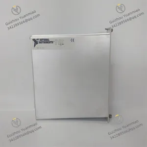
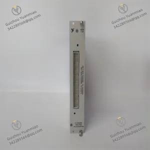
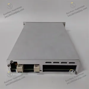
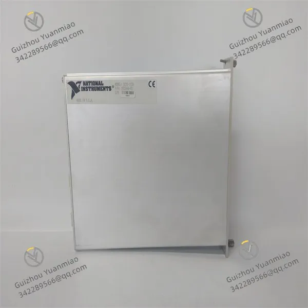
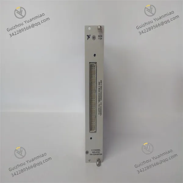
NI SCXI-1124 Analog Output Module
Related Products
I. Product Overview
National Instruments SCXI-1124 (Part Number: 776572-24) is a 6-channel isolated analog output module specifically designed for the SCXI signal conditioning system and compatible with PXI/SCXI hybrid chassis. Its core function is to convert digital signals into high-precision, isolated DC voltage or current analog signals, which are used to drive actuators, control industrial processes, or simulate sensor signals. Equipped with features including independent channel configuration, high isolation, low noise, and software programmability, this module seamlessly integrates with development environments such as LabVIEW and LabWindows/CVI via the NI-DAQmx driver software. It is widely applied in fields like industrial automation, test and measurement, scientific research experiments, medical device control, and manufacturing calibration and verification.
Adopting a 6U standard size design, the module supports multi-module expansion. A single DAQ device can control multiple SCXI-1124 modules through the SCXI bus. With its 12-bit resolution, flexible output range configuration, and relay service life of 10 million cycles, it serves as a core solution for scenarios requiring isolated signal output, ensuring the accuracy of signal transmission and the safety of system operation.

II. Functional Features
6-Channel Independent Isolation and Flexible Output Configuration
High Precision and High Stability Performance
Flexible Expansion and System Integration Capability
Convenient Operation & Maintenance and Reliable Design
Full-Scenario Adaptability and Core Functions
III. Technical Parameters
IV. Working Principle
V. Operation Guide
1. Installation StepsInstallation Environment
Mechanical Installation
Wiring Specifications
2. Configuration and Debugging
Software Installation and Driver Configuration
Channel Parameter Configuration
Power-On Debugging
3. Operation and MaintenanceStatus Monitoring
Regular Maintenance
4. Common Fault Troubleshooting

Send Inquiry to This Supplier


You May Also Like
-
NI SCXI-1349 Cables/AdaptersNegotiableMOQ: 1 Piece
-
NI PXI-8186 Embedded ControllerNegotiableMOQ: 1 Piece
-
NI PCI-6224 GPIB ControllerNegotiableMOQ: 1 Piece
-
NI SCXI-1327 High-Voltage Attenuator Terminal BlockNegotiableMOQ: 1 Piece
-
NI SCXI-1346 ChassisNegotiableMOQ: 1 Piece
-
NI SCXI-1126 8-Channel Frequency Input ModuleNegotiableMOQ: 1 Piece
-
NI BNC-2110 Series Shielded Connector BlocksNegotiableMOQ: 1 Piece
-
NI GPIB-140A GPIB Interface DeviceNegotiableMOQ: 1 Piece
-
NI-9505 Series Motor Drive ModuleNegotiableMOQ: 1 Piece
-
NI-9853 Controller Area Network (CAN) InterfaceNegotiableMOQ: 1 Piece


