








 Contact Platform Support
 Help Center
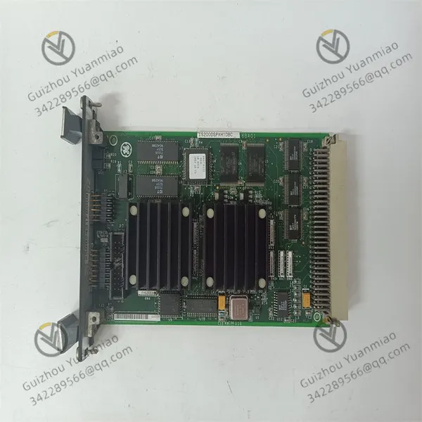
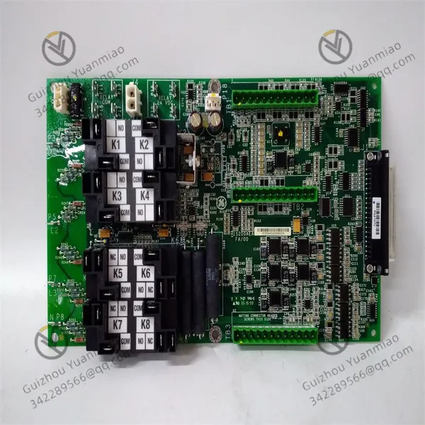
GE IS200MVRCH1ABA Analog Input/output Board

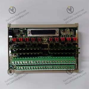
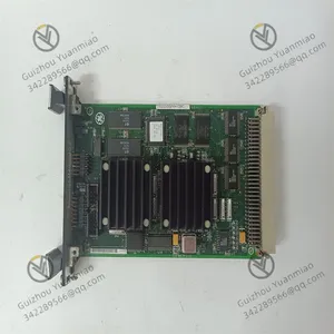
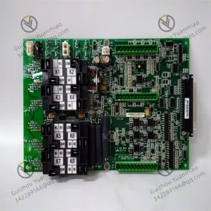
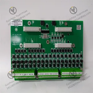





Related Products
-
 GE IS200MVRDH1AAB Signal Processing ModuleNegotiableMOQ: 1 Piece
 -
GE IS215WECAH1A Turbine Control System ComponentsNegotiableMOQ: 1 Piece
-
GE IS215VPROH2B Emergency Turbine Protection PlateNegotiableMOQ: 1 Piece
-
GE IS215VAMBH1A Mark VI Series Acoustic Monitoring BoardNegotiableMOQ: 1 Piece
-
GE IS415UCVHH1A VME Control BoardNegotiableMOQ: 1 Piece
GE IS200MVRCH1ABA analog input/output board
I. Module Positioning and System Architecture
1. System and role to which one belongs
System affiliation: As an EX2100 series module, it is highly likely to be compatible with GE's Mark V/Mark VI turbine control systems (such as the Speedtronic series), or used in distributed control systems (DCS) and programmable logic controller (PLC) systems in industrial automation.
Functional role: Referring to the similar model IS200MVRCH1A (analog input/output board), it is speculated that its core functions are signal acquisition, processing and transmission. It may serve as a base board or interface board and work in coordination with other functional modules (such as processor board, communication board).
2. Hardware architecture foundation
Physical interface: It may have 14 ports (such as marked with JDD, JAR, etc.) for connecting sensors, actuators or other modules, and supports cable plug-and-pull connection.
Installation method: Fixed in the frame or control cabinet through 8 base installation holes and 4 HSLA installation holes, in compliance with industrial standard installation specifications.
Power supply and indicator lights: It may rely on an external power supply (such as DC 24V or AC 220V), but depending on similar models, it may not have an LED indicator light itself and the status needs to be displayed through other system modules.
Ii. Core Working Principle: The entire process of signal processing
1. Analog signal input and acquisition
Input type: Receive analog signals from on-site sensors (such as 4-20mA current signals, 0-10V voltage signals), commonly found in temperature sensors, pressure transmitters, flow meters, etc.
Signal conditioning: Through on-board capacitors, resistors, operational amplifiers and other components, the input signal is filtered, amplified and anti-interference processed to avoid noise affecting data accuracy.
High-speed sampling: Referring to similar modules (such as high-speed scanning modules used for turbine control), it can synchronously sample multiple signals at a millisecond rate (such as 1ms) to ensure real-time performance.
2. Analog-to-digital Conversion (A/D conversion)
Conversion mechanism: Built-in A/D converter converts analog signals into digital signals (such as 12-bit or 16-bit binary data), facilitating processing by the processor.
Accuracy and resolution: The conversion accuracy may reach ±0.1% FS (full scale), meeting the accuracy requirements for parameter monitoring in industrial control.
3. Data processing and temporary storage
Preprocessing logic: It may integrate simple logical operation units to normalize and linearize the data (such as nonlinear correction of temperature signals), or perform threshold judgment (such as over-limit warning).
Storage mechanism: Real-time data or configuration parameters are temporarily stored through on-board memory (such as EEPROM or RAM). In some scenarios, a backup power supply (such as lithium batteries) is relied upon to prevent data loss in case of power failure.
4. Digital signal output and control
Analog-to-digital conversion (D/A conversion) : If it has an output function, the digital control instructions issued by the processor can be converted into analog signals (such as 4-20mA) to drive actuators (such as control valves, frequency converters).
Switching output: It may support digital output (such as relay contacts, transistor output), which is used to control the start and stop of equipment or trigger alarm signals.
5. Communication and system interaction
Bus communication: Communicate with the main controller via VMEbus, PCIe or dedicated industrial buses (such as GE's Genius Bus) to transmit collected data or receive control instructions.
Protocol support: It may be compatible with industrial communication protocols such as Modbus, Profibus, EtherNet/IP, etc., to achieve interconnection with other devices.
Synchronization mechanism: In high-speed control systems such as turbines, the timing consistency of multi-module data acquisition is ensured through hardware clocks or synchronization signals (such as 1ms pulses).
Iii. Working Logic in Typical Application Scenarios
1. Application in turbine control systems
Data acquisition: Connect the vibration sensor and temperature sensor of the turbine to collect parameters such as shaft vibration and bearing temperature in real time. After A/D conversion, the data is transmitted to the main controller.
Closed-loop control: The main controller calculates the regulation amount based on the rotational speed signal, converts it into an analog signal through IS200MVRCH1ABA, and controls the opening degree of the steam turbine's speed-regulating valves to achieve stable rotational speed.
Fault protection: When the collected parameters (such as shaft displacement) exceed the threshold, the module triggers digital output and links the shutdown protection circuit to ensure the safety of the equipment.
2. Application in industrial process control
Temperature control of chemical reaction vessels: Collect the temperature analog signal from the thermocouple, convert it into a digital value and send it to the PLC. The PLC calculates the heating/cooling instructions based on the PID algorithm, and then converts it into a 4-20mA signal through the module to control the opening degree of the regulating valve.
Sewage treatment flow regulation: Collect the flow signal of the electromagnetic flowmeter, process it through the module, compare it with the set value, and output the control signal to the frequency converter to adjust the speed of the water pump to maintain a stable flow.
Iv. Key Technical Features and Design Logic
Anti-interference design
Electrical isolation: The input/output ports may adopt optocoupler isolation or transformer isolation to prevent strong electrical interference on site from affecting the operation of the module.
Filtering circuit: High-frequency noise is reduced through LC filtering and EMI suppression circuits to ensure the purity of the signal.
2. Reliability mechanism
Potentiometer design: By referring to similar models, the module may not require manual calibration. Long-term accuracy is guaranteed through factory pre-calibration and digital compensation algorithms, reducing maintenance costs.
Wide temperature adaptability: Industrial-grade modules typically support operating temperatures ranging from -20 ℃ to +70℃, making them suitable for harsh industrial environments.
3. Collaboration with other modules
As a substrate: If used as the substrate for components such as IS210MVRCH1A, it may provide power distribution and signal routing functions, and support the insertion and communication of upper-layer modules.
Redundant design: In critical systems, dual-machine hot standby (such as master/slave mode) may be supported, ensuring seamless switching in case of system failure through data synchronization between modules.

Send Inquiry to This Supplier


You May Also Like
-
GE IS215ISBBH2A Communication SwitchNegotiableMOQ: 1 Piece
-
GE IS420UCSCH1A High-performance ControllerNegotiableMOQ: 1 Piece
-
The Working Principle of the GE IS220PAICH1B Mark VIe Analog I/O ModuleNegotiableMOQ: 1 Piece
-
GE IS220PDIAH1B Digital Input ModuleNegotiableMOQ: 1 Piece
-
GE IS220PDOAH1B Mark VIe Digital Output ModuleNegotiableMOQ: 1 Piece
-
GE IS220PTURH1B Turbine Speed Monitoring ModuleNegotiableMOQ: 1 Piece
-
GE DS200TCPDG1B Gas Turbine Control System ComponentNegotiableMOQ: 1 Piece
-
GE DS200IIBDG1A Digital Input Interface BoardNegotiableMOQ: 1 Piece
-
GE DS200TCEAG1BTF Mark VIe Control System ComponentNegotiableMOQ: 1 Piece
-
GE DS215TCQAG1BBF Redundant Controller ModuleNegotiableMOQ: 1 Piece


