

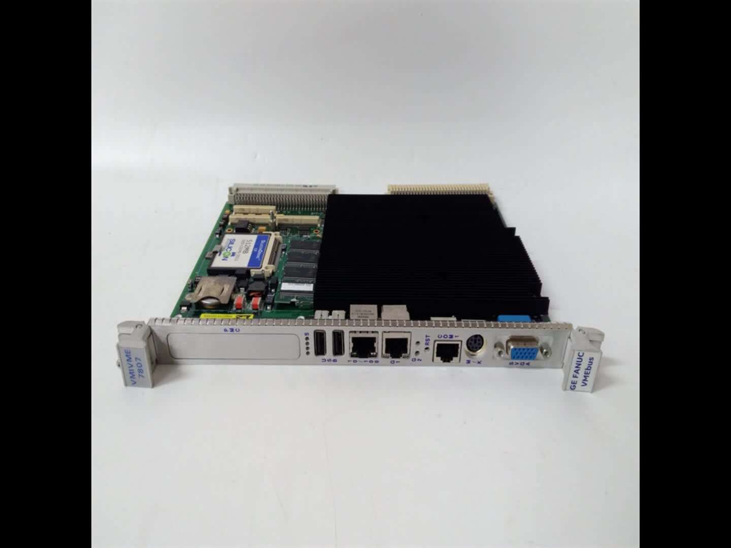
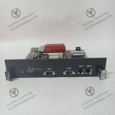
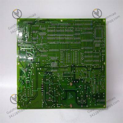
GE IS215ISBBH2A Communication Switch

Related Products
-
 GE IS420UCSCH1A High-performance ControllerNegotiableMOQ: 1 Piece
 -
The Working Principle of the GE IS220PAICH1B Mark VIe Analog I/O ModuleNegotiableMOQ: 1 Piece
-
GE IS220PDIAH1B Digital Input ModuleNegotiableMOQ: 1 Piece
-
GE IS220PDOAH1B Mark VIe Digital Output ModuleNegotiableMOQ: 1 Piece
-
GE IS220PTURH1B Turbine Speed Monitoring ModuleNegotiableMOQ: 1 Piece
Common troubleshooting methods
I. Troubleshooting of Power Supply Faults
Fault phenomenon: The equipment has no Power supply and the power indicator light (such as Power LED) does not light up.
Elimination steps:
Check the power input: Confirm whether the 24VDC power adapter is supplying power normally. Use a multimeter to measure whether the input voltage is within the rated range (a fluctuation of ±10% is normal).
Check the power cord connection: Inspect whether the power cable is loose, damaged or has poor contact. You can try replacing the power cord or re-plugging and unplugging the interface.
Test the power module: If the device supports the replacement of the power module, a spare power module can be replaced. Observe whether the indicator light is on to determine if the power module is damaged.
Ii. Troubleshooting Network Connection Issues
Fault phenomenon: The Ethernet port indicator light is not on, or communication with other devices is impossible.
Elimination steps:
Check the physical connection:
Check if the network cable is plugged in tightly and if the crystal head is damaged. You can replace the network cable for testing.
Confirm the port status: Check if the LED indicator light of the Ethernet port on the front panel (such as the Link/Act light) is flashing normally. If it remains on but does not flash, it may indicate that the link has not been established. If it does not light up, check the physical connection or port configuration.
Test port function:
Try to connect the port to a known normal device (such as a computer) and test the network connectivity through the ping command (for example, ping the IP address of the switch to see if there is a response).
If a single port fails, you can try restarting the device or resetting the port configuration through the management interface.
Check the routing configuration:
If static routing or dynamic routing configuration is involved, confirm whether parameters such as IP address, subnet mask, and gateway are correct. You can log in to the switch through the Web management interface or serial port to check the configuration.
Iii. Troubleshooting Hardware Faults
Fault phenomenon: Abnormal heating of the equipment, abnormal internal noise, or abnormal indicator light (such as constantly on, abnormal flashing frequency).
Elimination steps:
Visual inspection:
Check if the casing has any deformation or charring marks, and if the internal components (such as relays and coils) are loose or damaged. If any abnormality is found, power off immediately and replace it.
Check the status of the "receiver active" LED indicator light on the front panel: If this light is not on, it may be that the upstream branch transmission is interrupted or there is a cable fault. It is necessary to check the optical fiber or cable connection.
Heat dissipation and environmental inspection
Confirm whether the operating temperature of the equipment is within the range of 0℃ to 45℃ to prevent hardware damage caused by high temperature. Clean the dust from the heat dissipation holes of the casing.
Redundant function test
If the device supports dual power supply or dual port redundancy, you can disconnect the main power supply or main port and observe whether it automatically switches to the redundant path. If it does not switch, it may be that the redundant module is faulty and the component needs to be replaced.
Iv. Troubleshooting Communication Anomalies
Fault symptoms: High data transmission delay, severe packet loss, or failure of multicast routing function.
Elimination steps:
Network load detection
Check the port bandwidth utilization through the management interface. If it remains above 80% continuously, it may be due to network congestion causing packet loss. It is necessary to optimize the network topology or increase the bandwidth.
Multicast routing configuration check:
Confirm whether the multicast routing protocol (such as PIM-SM) is correctly enabled and whether the multicast group address configuration is consistent with that of other devices. You can analyze whether the multicast data packets are transmitted normally through packet capture tools (such as Wireshark).
Diagnostic tool usage:
Use the diagnostic functions built into the device (such as log recording and alarm output in the Web management interface) to check if there are any Error codes or abnormal event records, such as "Link Down", "CRC Error", etc. Locate the fault points (such as network cable interference, port hardware failure) according to the prompts.
V. System Reset and Upgrade
Fault phenomenon: Configuration errors cause abnormal equipment, or outdated software versions lead to compatibility issues.
Elimination steps:
Restore factory Settings
Perform the reset operation through the back jumper switch or the management interface (note to back up the configuration data), and reconfigure the network parameters and routing rules.
Firmware upgrade
Download the latest firmware from the GE official website, upgrade through the serial port or Ethernet interface, and fix known bugs or improve performance (ensure a stable power supply before upgrading to avoid power outages in the middle).
Vi. Maintenance and Preventive Measures
Regular inspection: Check the status of equipment indicator lights, power supply voltage, temperature and connecting cables every month, and record the operation data for comparison.
Spare parts management: Stock up on vulnerable parts such as power modules and network cables to facilitate the quick replacement of faulty components.
Environmental optimization: Ensure the installation environment is dry and dust-free, avoid strong electromagnetic interference, and fix the guide rails firmly during installation to prevent the interfaces from loosening due to vibration.

Send Inquiry to This Supplier


You May Also Like
-
GE DS200TCPDG1B Gas Turbine Control System ComponentNegotiableMOQ: 1 Piece
-
GE DS200IIBDG1A Digital Input Interface BoardNegotiableMOQ: 1 Piece
-
GE DS200TCEAG1BTF Mark VIe Control System ComponentNegotiableMOQ: 1 Piece
-
GE DS215TCQAG1BBF Redundant Controller ModuleNegotiableMOQ: 1 Piece
-
GE DS200TCDAH1BHD Communication Interface ModuleNegotiableMOQ: 1 Perch
-
GE DS200DCFBG1ALC DC Power Supply ModuleNegotiableMOQ: 1 Piece
-
GE IC660BBD022 Distributed I/O ModuleNegotiableMOQ: 1 Piece
-
GE IC660EBD025 Mark VI Series Processor BoardNegotiableMOQ: 1 Piece
-
GE IC660ELB912 I/O System ModuleNegotiableMOQ: 1 Piece
-
GE IC660ELB912J Network Interface ModuleNegotiableMOQ: 1 Piece


