








 Contact Platform Support
 Help Center
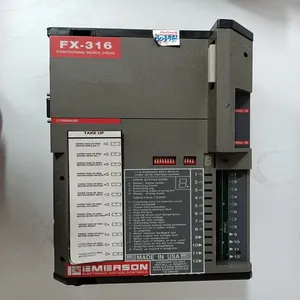
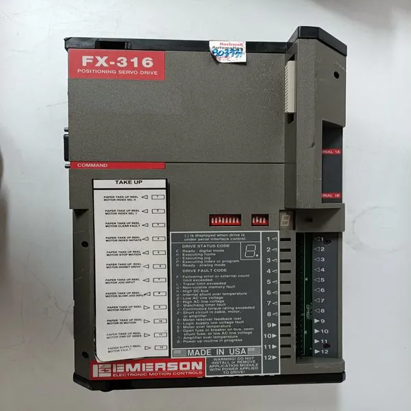
FX-316


Related Products
Brand: EMERSON
Type:FX-316
Origin: the United States
Warranty: 365 days
Colour: new/used
Shipping method: Courier delivery
The CPUs are supplied with internal back-up batteries. When the batteries are to be used, place them in the Internal Battery Holder (Figure 63 on page 193). When the external SB821/SB822 battery units are to be used, install them according to the instructions in Installing the SB821 External Battery Unit on page 143/Installing the SB822 Rechargeable External Battery Unit on page 144. Do not place the internal back-up battery in the battery holder until the AC 800M Controller has been powered-up normally and the memory back-up function has been activated, that is, the B(attery) LED flashes. If no normal power supply is connected to the processor unit with the battery in place, then the CPU memory will immediately start to consume battery power. Always install a fresh internal or external battery at the end of the installation phase. The original battery is heavily utilized due to frequent blackouts during system installation.
In redundant configuration, two PM891 units are mounted on two separate DIN-rails. If sufficient space is available, the units can be mounted on the same DIN-rail. Use the following procedure to install the processor units along the DIN-rail: 1. Mount the processor units. 2. Mount the communication interfaces on the CEX-Bus to the left of the processor unit. If BC810s are used, the configuration of the segments should be considered. If no BC810s are used, the interfaces can be divided between the two CPUs in any preferred way. 3. Press the units gently together and ensure that the CEX-Bus is correctly connected, through the connector on the unit. 4. If BC810s are used, connect the TK851 cable to the two BC810s.
 If no BC810s are used, mount the CEX-Bus extension cable TK850 to the units at farthest away from the processor units or, if no units are mounted, directly to the CEXBus on the processor unit. The CEX-Bus extension cable must be connected to both CPUs whether or not there are any other CEX-Bus units (Figure 29 on page 93). 5. Connect the RCU Data Link Cable (TK855) and the RCU Control Link Cable (TK856) to both CPUs. The RCU Data Link Cable (TK855) and the RCU Control Link Cable (TK856) must not be replaced by similar cables. Using another cable will disable the identification of the CPUs in the Control Builder and Operator Station. The CPU connected to the RCU Control Link Cable (TK856) connector marked “UPPER” will be defined as “UPPER” in the Control Builder and Operator Station. The marking has no relevance to the physical placement of the CPUs. Any CPU can become the Primary CPU.

Send Inquiry to This Supplier


You May Also Like
-
1C31194G01US$ 1074 - 2065MOQ: 1 Piece
-
VE3008 12P3439X012 KJ2003X1-BB1US$ 1083 - 2074MOQ: 1 Piece
-
K3NX-AD1A-FLK4US$ 1111 - 2021MOQ: 1 Piece
-
IS215VCMIH2CA IS200VCMIH2CAAUS$ 1111 - 2021MOQ: 1 Piece
-
PP885 3BSE069276R1US$ 1111 - 2021MOQ: 1 Piece
-
ORIENTAL MOTOR 2GK180KUS$ 1112 - 2022MOQ: 1 Piece
-
PACIFIC SCIENTIFIC 33VM52-000-4US$ 1112 - 2022MOQ: 1 Piece
-
TRICONEX 3625C1US$ 1112 - 2022MOQ: 1 Piece
-
DS200DCFBG1BLCUS$ 1112 - 2022MOQ: 1 Piece
-
F8650XUS$ 1112 - 2022MOQ: 1 Piece


