








 Contact Platform Support
 Help Center
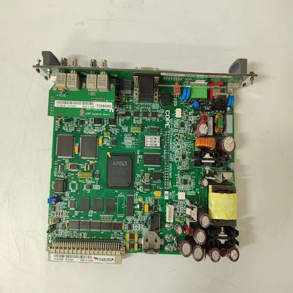
SY-1025115C SY-1025120E 0399143 SY-0301060R


Related Products
Brand:FOXBORO
Type:SY-1025115C SY-1025120E 0399143 SY-0301060R
Origin: the United States
Warranty: 365 days
Colour: new/used
Shipping method: Courier delivery
Spare parts spare parts, the main DCS control system of PLC system and the robot system spare parts,
Brand advantage: Allen Bradley, BentlyNevada, ABB, Emerson Ovation, Honeywell DCS, Rockwell ICS Triplex, FOXBORO, Schneider PLC, GE Fanuc, Motorola, HIMA, TRICONEX, Prosoft etc. Various kinds of imported industrial parts
In a redundant configuration an automatic switch-over from the Primary CPU to the Backup CPU occurs in the following situations, provided they are in synchronized state (DUAL LED is lit): • Memory error in the Primary CPU. • Other HW-error in the Primary CPU, which causes CPU crash. • Severe communication errors on the Control network, that is, loss of both network ports in the Primary CPU. • Severe communication errors on the ModuleBus (if ModuleBus is part of the HW configuration) that is, loss of clusters in the Primary CPU. Note that a Backup CPU with severe communication errors on the ModuleBus will be rejected (if ModuleBus is part of the HW configuration) and synchronized state will never be reached as long as error remains.
 To affirm, following start-up, that the AC 800M Controller and all associated units are operating correctly, see Table 23 on page 185. Verification of Single CPU Check the status of each LED indicator and compare it against the criteria listed in the table. If the status is other than that listed, see Fault-Finding Procedures on page 204.
To check that the redundancy, is working correctly, perform a manual switch-over from the Primary CPU to the Backup CPU. This should be performed with caution, and consideration to possible impact on the process.
A manual switch-over is initiated by: • Resetting the Primary CPU • Powering off the Primary CPU
The RCU Link Cable must NEVER be removed from the primary Processor Unit during redundant operation. Removal of the cable may cause the unit to stop.
Check that the yellow DUAL LED subsequently lights up on both CPUs, and that the PRIM LED lights up on the former Backup CPU now acting as Primary CPU. For other units see Table 23 on page 185.

Send Inquiry to This Supplier


You May Also Like
-
FBM207C RH917GYUS$ 1167 - 2067MOQ: 1 Piece
-
FBM219 RH916RHUS$ 1167 - 2067MOQ: 1 Piece
-
FBM237 RH914XSUS$ 1168 - 2068MOQ: 1 Piece
-
RH924YFUS$ 1168 - 2068MOQ: 1 Piece
-
FBM227 P0927ACUS$ 1206 - 2215MOQ: 1 Piece
-
SSA-T8028-0652US$ 1214 - 2223MOQ: 1 Piece
-
FBM233 P0926GXUS$ 1035 - 2255MOQ: 1 Piece
-
A4H254-8F8TUS$ 1068 - 2059MOQ: 1 Piece
-
FBM230 P0926GUUS$ 1076 - 2067MOQ: 1 Piece
-
A4H124-24TXUS$ 1081 - 2072MOQ: 1 Piece


