








 Contact Platform Support
 Help Center
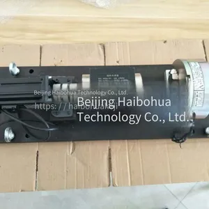
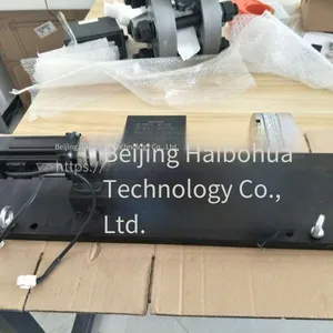
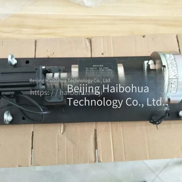
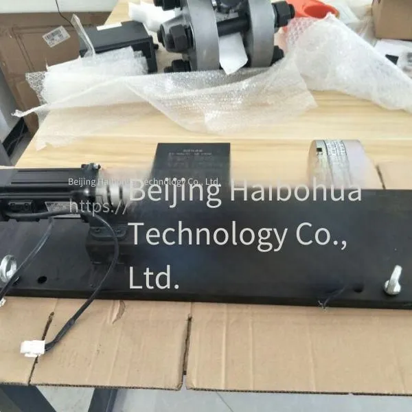
High-speed Motor Test Bench



Related Products
-
 Special Torque Sensor for Teaching, Dedicated for Motor Testing and Reducer Test BenchUS$ 553.85 - 569.23MOQ: 1 Set
 -
Dynamic Torque Sensor, Motor Testing, Reducer Torque and Speed Sensor, Beijing HaibohuaUS$ 553.85 - 569.23MOQ: 1 Unit
-
Pneumatic Motor Test Bench, Hydraulic Motor Test Bench, Beijing HaibohuaUS$ 2769.23 - 2923.08MOQ: 1 Set
-
Chb Force Value Display and Control Instrument, Haibo HuaNegotiableMOQ: 0 Unit
-
Which Torque Sensor is Used for Stirring? Axial Installation Torque Sensor Specially Designed for the Stirring Industry, Haibo HuaUS$ 584.62MOQ: 1 Piece
I. Overview
High-speed motor test bench
The motor test system is designed for motor performance tests. It measures performance parameters such as the voltage, current, torque, speed, input and output power, and efficiency of the motor, prints test reports, and draws various performance curves.
The torque and speed sensor measures the output torque and speed of the motor. The load uses a magnetic powder brake (or an eddy current dynamometer. This system takes the magnetic powder brake as an example). The voltage and current are converted into standard voltage signals using a power transducer and collected by the computer.
The measurement items that the system can complete include: the input voltage and current of the motor, output torque, speed, efficiency calculation, etc. The output report and curve format can be customized according to national standards or user requirements. The system is built on a computer. All sensor output signals are directly connected to the computer through various acquisition cards (torque, speed, and power measurement cards, A/D cards), and the control signals are directly used by the computer to control the mechanism actions through various control cards (I/O cards, D/A cards).
This system consists of a control cabinet and a test bench (Figure 1).
(I) Control cabinet
1. 15` touch screen industrial control computer
2. Magnetic powder brake controller (or eddy current dynamometer controller)
3. Motor multi-parameter measurement system
4. Intelligent analog acquisition module
5. Power sensor power module
6. Variable frequency drive
7. The variable frequency drive controller can be externally connected to a printer
(II) Test bench
1. Install the base mechanical platform
2. HCNJ-101 Torque Sensor
3. Magnetic powder brake load
4. Movable motor clamping frame
5. Coupling, support frame, and terminal block
6. Isolated current sensor
7. Isolated voltage sensor
II. Functions and Technical Specifications
(1) System functions
1. The system can conduct the following tests on the motor: No-load test: current, voltage, speed; Load test: current, voltage, torque, speed, input power, output power, efficiency; Locked-rotor test: current, voltage, torque
2. The system can test specific points of various motors.
3. The system can display the motor's voltage, current, input power, torque, speed, output power, and efficiency in real-time.
4. The system can automatically identify and display positive and negative torques.
5. The system can set upper and lower limit alarms for current, voltage, torque, and speed respectively, and the alarm values can be set arbitrarily.
6. The system can continuously store the test data or store selected points according to the user's wishes.
7. In the "selected-point measurement" mode, the system can display the collected data and curves in real-time.
8. The system can draw curves of torque - current, voltage, speed, power, and efficiency based on the test results.
9. The system has a memory function for the settings of various parameters, and only needs to be input once.
10. Data editing and modification are allowed, and the system has a historical data playback function.
11. The system can print data and curves of test results through a printer.
12. The entire function of the system can be operated through both menus and shortcuts.
13. The system runs in the WINDOWS environment, and the entire interface is vivid and beautiful.
(2) Technical indicators
1. Voltage measurement accuracy: ±0.5%FS
2. Voltage display accuracy: 1 decimal place
3. Current measurement accuracy: ±0.5%FS
4. Current display accuracy: 2 decimal places
5. Electric power calculation accuracy: ±1 digit
6. Electric power display unit: kW
7. Torque measurement accuracy: better than ±1%FS
8. Torque measurement range: 0~100N.m
9. Torque display accuracy: 3 decimal places
10. Rotational speed measurement accuracy: ±0.1% above 50r/min, ±0.5% below 50r/min
11. Rotational speed display accuracy: 1 decimal place
12. Rotational speed display unit: r/min
13. Power calculation accuracy: ±1 digit
14. Power display unit: kW
15. Efficiency calculation accuracy: ±1 digit
16. Efficiency display accuracy: 2 decimal places
17. Efficiency display unit: %
18. Alarm value range: The upper and lower limits can be set arbitrarily.
III. Structure overview
1. Test bench: It consists of an installation base mechanical platform, measurement sensors, a magnetic powder brake, and a lifting mechanism. (See Figure 2, taking the 2000Nm torque sensor and supporting equipment as an example)
2. Control cabinet: It is composed of a horizontal or vertical cabinet, and inside it are installed control circuits, a 15` touch-screen industrial control computer, a magnetic powder brake controller, a variable frequency governor, a variable frequency governor controller, and a sensor measurement and acquisition system.
3. Load: It is composed of a magnetic powder brake. A magnetic powder brake is a rotating machine with two relatively moving parts, the stator and the rotor. Both the stator and the rotor are made of magnetic permeability materials. The working gap between the stator and the rotor is filled with magnetic powder. When the exciting coil on the stator is energized with an exciting current, the magnetic powder aggregates to form a magnetic powder chain. The torque is transmitted by the magnetic bonding between the powders and the frictional force between the powders and the two moving parts. As the exciting current increases, the transmitted torque also increases. When the exciting current increases to a certain value, the magnetic permeability material reaches magnetic saturation, and the transmitted torque also reaches a saturated state. When the exciting current is interrupted, the magnetic powder loses its restraint and is in a loose state. Therefore, basically no torque is transmitted. Before testing the magnetic powder brake, water must be supplied first. After testing, the water supply can be stopped until the temperature drops. The surface temperature of the magnetic yoke should be controlled at ≤85oC. If the temperature is too high, a blower should be used for cooling, or the inlet water temperature should be lowered. Especially in summer, the heat dissipation conditions should be improved.
4. Coupling: Rigid connection (flange, shaft sleeve) is adopted to ensure measurement accuracy
5. Sensors: The HCNJ - 101 torque sensor measures the output speed and torque of the motor, and the isolated current and voltage sensors measure the input current and voltage of the motor.
6. Installation base and lifting mechanism: The base uses a standard platform with standard T-slots on the platform and a smooth surface. The installation unevenness of the flat plate is less than 0.05mm. The base should be stable to avoid excessive vibration, otherwise the data testing will be inaccurate. The lifting mechanism is composed of 20 - 30mm steel and M16 - M30 screw nuts. During lifting, the adjustment can be completed by adjusting the nuts. During testing, the lifting mechanism must be tightened to prevent excessive vibration. During installation, adjust the lifting steel plate according to the height of the motor. Pay attention to the coaxiality to avoid the additional bending moment caused by the deformation of the sensor. When there is a bending moment, it will not only reduce the testing accuracy, but in some cases, it may even damage the deformed shaft.
Specific method: First, connect the motor well without tightening the motor base. Turn the sensor and the motor by hand, and they should move smoothly without any slight displacement. When turning, it should feel smooth. If the installation coaxiality does not meet the requirements, adjust the lifting steel plate until it meets the requirements. Finally, tighten the motor and the studs of the lifting steel plate.
7. Loading control:
(1) The computer uses the D/A module to adjust the output current of the controller to achieve automatic loading by the computer.
(2) Controller unit: Use the PWM adjustment module to output current for precise adjustment.
(3) When exiting the system, the system will adjust the output current of the controller to the minimum. Compare the set value with the current feedback, and adjust the solid-state relay through proportional (P), integral (I), and differential (D) to control the pulse width to adjust the magnitude of the excitation current. When the set value remains unchanged, the excitation current remains unchanged (constant current source). Since the solid-state relay uses a field-effect transistor as the switching element inside, there is no mechanical action and no spark interference, so the reliability is high.
8. Motor speed control: The computer software sets the motor speed, and then the motor speed is controlled through the variable frequency speed controller and the variable frequency speed governor.

Send Inquiry to This Supplier


You May Also Like
-
Special for Beijing Haibohua Hcnj - 102, Double - Flange Static Torque Sensor Actuator Test BenchUS$ 184.62 - 200MOQ: 1 Piece
-
Wlk-3a Controller Switch Type With Magnetic Powder Brake and Eddy Current Brake, Using Haibo HuaUS$ 169.23MOQ: 1 Unit
-
Beijing Display Instrument Multi-channel Thermal Meter Xsd2, Manufacturer: Haibo HuaNegotiableMOQ: 0 Unit
-
Small Torque Sensor for Electric Motors, Small-range Dynamic Torque SensorUS$ 692.31 - 723.08MOQ: 1 Piece
-
Single-channel Thermal Instrument With High Precision Xse, Beijing HaibohuaNegotiableMOQ: 0 Unit
-
Xsw Single-channel Thermal Instrument Display Meter, Manufactured by Beijing HaibohuaNegotiableMOQ: 0 Unit
-
Ch6 Single-channel Thermal Instrument by Beijing HaibohuaNegotiableMOQ: 0 Unit
-
Xst Single-channel Industrial Meter, Beijing HaibohuaNegotiableMOQ: 0 Unit
-
Hydraulic Motor and Pneumatic Motor Test Bench, Beijing HaibohuaUS$ 2769.23MOQ: 1 Set
-
Paperless Recorder Xsr90, Beijing HaibohuaNegotiableMOQ: 0 Unit


