Product Description
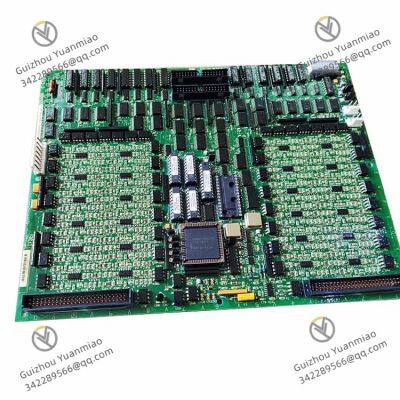
The GE DS200TCDAH1BJE is a core digital input/output (I/O) module of General Electric (GE)’s Mark V series gas turbine/steam turbine control system. Specifically designed for the control of large rotating machinery in energy sectors such as thermal power plants and gas-fired power stations, this module serves as a "bridge" for signal interaction between unit control systems and on-site equipment. It undertakes the functions of collecting digital signals (input) and executing control commands (output), making it a critical hardware component for ensuring unit start-stop, load adjustment, and safety interlocking. It features high reliability, anti-interference capability, and industrial-grade environmental adaptability.
I. Basic Information and Core Positioning1. Interpretation of Model and Product Identification
The model naming of GE Mark V series I/O boards follows the logic of "system affiliation + function type + hardware version". The specific meaning of the DS200TCDAH1BJE identification is as follows:
DS200: Prefix for the Mark V system hardware platform, indicating that this module belongs to GE’s classic Mark V control system (suitable for large turbine control), distinguishing it from subsequent upgraded series such as Mark VIe.
TCDA: Function code, corresponding to a "combined digital I/O module" (T=Type, CDA=Combined Digital Analog; specifically referring to mixed digital input/output functions here. Variations in suffixes of some models correspond to pure input or pure output versions).
H1BJE: Hardware version and configuration code, including component batch, interface details, and compatibility identifiers (e.g., "H1" represents a specific hardware revision, and "BJE" is the production configuration code). Versions with different suffixes usually have slight optimizations in component selection, but their core functions and installation dimensions remain compatible.
2. Core Application Scenarios
As the "on-site signal interaction unit" of the Mark V control system, this module is exclusively compatible with the GE Mark V turbine control system, primarily used in:
Gas turbine/steam turbine control: Collecting status signals from on-site equipment (e.g., valve limit switches, motor start-stop feedback) and outputting control commands (e.g., solenoid valve actions, indicator light driving).
Unit safety interlocking: Accessing emergency shutdown (ESD) signals and overspeed protection switch signals to ensure rapid triggering of safety logic in case of faults.
Auxiliary system control: Adapting to digital signal interaction in turbine lubricating oil systems and cooling systems (e.g., pump operation status monitoring, solenoid valve control).

II. Key Technical Parameters1. Electrical Performance Parameters
2. Environmental and Physical Parameters
III. Core Functions and Technical Characteristics1. Digital Signal Interaction and Control
As a "signal transfer station" between the Mark V system and on-site equipment, it enables bidirectional digital signal processing:
Digital input collection: Receives status signals from on-site equipment (e.g., "open/closed" feedback of valves, "normal/alarm" status of pressure switches) through photoelectric isolation circuits, converts dry contact/wet contact signals into logic levels (0/1) recognizable by the system, and filters high-frequency noise (built-in RC filter circuit with configurable filter time constant via software).
Digital output control: Drives relay contacts to actuate according to commands from the Mark V main controller, outputting control signals to actuators (e.g., starting lubricating oil pumps, closing fuel valves). At the same time, it monitors whether the output channels are functioning normally (e.g., relay sticking detection) through the "contact status feedback" function, ensuring the effective execution of control commands.
2. High Reliability and Safety Design
To meet the requirement of "continuous operation with zero faults" in power stations, the module enhances reliability at both hardware and software levels:
Isolation protection: Both input and output channels adopt photoelectric isolation, which is completely isolated from the internal circuits of the system. This prevents high-voltage/strong interference signals from on-site from intruding into the main controller, avoiding system crashes or component damage.
Fault self-diagnosis: Built-in hardware diagnostic circuits can real-time monitor input power, relay contact status, and isolation circuit integrity. If a fault is detected (e.g., missing input power, open relay coil), it immediately sends a fault code (e.g., "DI Channel 3 Fault", "DO Relay 2 Stuck") to the host computer via the Mark V system bus and lights up the module fault indicator (LED), facilitating maintenance personnel to quickly locate the problem.
Redundancy configuration support: Supports dual-module redundancy (1+1) configuration. When the main module fails, the standby module switches automatically (switching time ≤ 100ms), ensuring uninterrupted signal collection and control output to meet the safety operation requirements of the unit.
3. System Compatibility and Configuration Flexibility
Bus communication: Communicates with the main controller (e.g., DS200CPU module) via the Mark V system-specific backplane bus (such as GE Genius Bus or Modbus slave bus) with a data transmission rate of ≤ 1Mbps and a communication delay of ≤ 5ms, meeting real-time control requirements.
Software configuration: The GE-specific configuration software (e.g., Mark V Toolbox) is used to set the input channel type (dry contact/wet contact), output relay action logic (normally open/normally closed), filter parameters, etc. No hardware wiring modifications are required, adapting to the needs of different on-site equipment.
Backward compatibility: Fully compatible with other modules of the Mark V system (e.g., analog I/O board DS200TAMA, power module DS200PCCAG1A), and can directly replace older versions of modules in the same series (e.g., DS200TCDAH1BJD) without adjusting the rack or software.
IV. Compatible Equipment and Maintenance Guidelines1. Compatible GE Turbine Control Systems and Units
This module is exclusively used in the GE Mark V control system and is mainly compatible with the following units:
Gas turbines: GE 9FA, 9E, 7FA, and other series of heavy-duty gas turbines.
Steam turbines: GE 300MW, 600MW class thermal power steam turbines.
Combined cycle units: Integrated control of GE multi-shaft/single-shaft combined cycle power plants.
2. Installation and Maintenance Guidelines
Installation requirements: Must be installed in a Mark V system standard cabinet, avoiding direct sunlight, dust accumulation, and corrosive gases. A gap of ≥ 5mm must be reserved between modules to ensure good heat dissipation. When wiring, distinguish between input/output power supplies (DC 5V/DC 24V) to prevent component damage caused by reverse connection.
Replacement process: Before replacement, cut off the module power supply (DC 5V and DC 24V), unplug the backplane bus connector. After installing the new module, restore parameters via the configuration software (or download the configuration from the main controller) and perform a "channel test" (e.g., manually triggering the output relay to verify the action of on-site equipment).
Calibration and periodic maintenance: Conduct a channel function test every 1–2 years (using a signal generator to simulate input signals and monitor the status of output contacts); inspect the wear of relay contacts every 3 years. If the contacts are oxidized or ablated, replace the relay module in a timely manner (can be replaced individually without replacing the entire PCBA).
Spare part storage: Store spare parts in a dry, normal-temperature environment (temperature 15–25℃, humidity 30%–60%) to avoid electrostatic damage (store in anti-static packaging bags). Conduct power-on tests regularly (every 6 months) to ensure the availability of spare parts.


ABB CHBX01L 2VAA008574R1 Compact Bus Extender
ABB CHBX01R 2VAA008575R1 Compact Bus Extender
ABB UFC921A 3BHE024856P106 Communication Module
ABB PP886 3BSE092980R1 Operation Panel
ABB SUE3000 1VCF750090R0804 Maintenance Exchange Unit
ABB SUE3000 1VCR007346 G0032 REF542plus HMI Unit
ABB GFD563A101 Interface Module
ABB 3BHE046836R0101 Interface Module
ABB UNS0881b-PV2 PCB Circuit Board
ABB 3BHE050077R0102 PCB Circuit Board
ABB 500PB101 1MRB200064/C Binary Output Module
ABB 1MRB178009R0001 Binary Output Module
 yezi
Hi there! Welcome to my shop. Let me know if you have any questions.


