

Home > Electrical & Electronics > Electrical Control System > ABB ASE2UDC920AE01 3BHB022793R0001 Digital Module
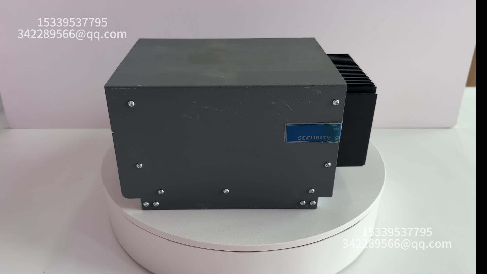
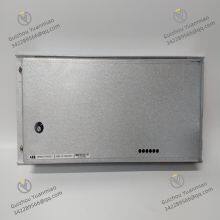
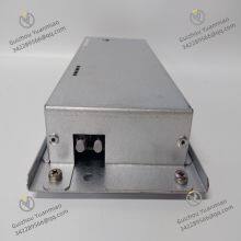
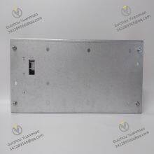
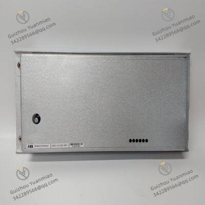
ABB ASE2UDC920AE01 3BHB022793R0001 Digital Module
Negotiable
MOQ: 1 Piece (Price negotiable depending on order volume and customization)
Key Specifications
Get Latest Price
Material:
Other, Global universal model
Certification:
CE
Function:
Other, Global universal model
Payment & Shipping
Payment Methods:
Port of Shipment:
guizhou
Delivery Detail:
Delivery time depends on order quantity.
Related Products
-
 ABB NU8976A99 HIER466665R0099 HIEE320693R0001 Controller ModuleNegotiableMOQ: 1 Piece
 -
ABB 500CPU05 1MRB150081R1/E CPU ModuleNegotiableMOQ: 1 Piece
-
ABB 500CIM05 1MRB150077R1/B Communication ModuleNegotiableMOQ: 1 Piece
-
ABB 500MBA02 1MRB200053/M Controller ModuleNegotiableMOQ: 1 Piece
-
ABB 500SCM01 1MRB150004R0001 Coupler ModuleNegotiableMOQ: 1 Piece
Material
Other, Global universal model
Certification
CE
Function
Other, Global universal model
Condition
New
Task
Other, Global universal model
Mathematical Model
Other, Global universal model
Signal
Other, Global universal model
Customized
Non-Customized
Structure
Other, Global universal model
ASE2UDC920AE01 3BHB022793R0001 is the core Digital Input/Output (DI/DO) module of the UDC 920 series process control system developed by ABB Group (Switzerland). It mainly undertakes the functions of collecting and processing digital signals in industrial fields, as well as outputting execution commands. As such, it serves as a key hardware unit for the UDC 920 system to realize "equipment status monitoring, logical control, and safety interlocking".
Designed to meet industrial-grade requirements for high reliability, electromagnetic interference (EMI) resistance, and flexible scalability, this module is widely used in process control scenarios across industries including power, chemical engineering, metallurgy, and oil & gas. Typical applications include reactor temperature interlocking, pump/valve start-stop control, and equipment fault monitoring. Essentially, it acts as a "signal bridge" connecting on-site sensors/actuators to the main control unit of the UDC 920 system.
As the digital interface module of the UDC 920 system, this module is mainly used in "switch signal interaction" scenarios in industrial fields. Typical applications include:
Key Technical Parameters1. Digital Input (DI) Performance Parameters| Parameter Category | Specific Specifications |
|---|---|
| Number of Input Channels | 8 independent DI channels, supporting single-ended or differential input (selected via module jumpers). Electrical isolation between channels (500V AC for 1 minute) to prevent signal interference between channels. |
| Input Signal Type | - Dry contact input: Supports passive contacts (e.g., travel switches, limit switches) with a contact rating of ≤1A/250V AC. - Wet contact input: Supports active signals (e.g., NPN/PNP sensor outputs) with an input voltage range of DC 24V ±10% (compatible with industrial standard 24V sensors). |
| Input Response Time | Typical value ≤1ms (from signal trigger to module recognition), maximum response time ≤5ms, meeting the needs of rapid status monitoring (e.g., fault detection of high-speed equipment). |
| Input Impedance | Dry contact input: ≥10kΩ; Wet contact input: ≤1kΩ (ensures stable sensor signal input and prevents misjudgment caused by leakage current). |
| Overvoltage/Overcurrent Protection | Each DI channel has a built-in TVS (Transient Voltage Suppressor) diode (rated voltage 36V), capable of withstanding a DC 60V surge voltage (duration ≤100ms); a built-in current-limiting resistor (200Ω) prevents module damage due to overcurrent. |
| Parameter Category | Specific Specifications |
|---|---|
| Number of Output Channels | 4 independent DO channels, using relay output (Single-Pole Double-Throw, SPDT). Electrical isolation between channels (1000V AC for 1 minute). |
| Output Contact Rating | - Resistive load: 2A/250V AC or 2A/30V DC - Inductive load: 0.5A/250V AC or 0.5A/30V DC (external freewheeling diode required) - Lamp load: 1A/250V AC (compatible with industrial alarm lamps and indicator lamps) |
| Output Response Time | Relay pull-in time ≤10ms, release time ≤5ms, meeting the needs of medium-to-low speed control (e.g., pump/valve start-stop, heater control). |
| Output Protection Function | Each DO channel has a built-in overcurrent protection fuse (2.5A/250V AC), which automatically blows in case of load short circuit to protect the module's output circuit; relay contacts are made of silver alloy to enhance arc resistance and service life. |
| Parameter Category | Specific Specifications |
|---|---|
| Power Supply Requirements | - Module power supply: DC 24V ±10% (from UDC 920 system-specific power supply module, e.g., 3BHB013089R0001), ripple ≤100mV - Power consumption: ≤3W during normal operation (no output load), ≤8W at full-load output (4 channels with 2A load each) |
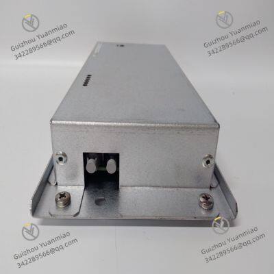
| Communication Interface | - System bus: Compatible with UDC 920 system-specific backplane bus (PROFIBUS DP slave protocol), maximum communication rate 12Mbps, data update cycle ≤10ms - Communication connector: 15-pin D-Sub plug (with locking screws), supporting hot swapping (operation required when the system is powered off or in "module offline" state) |
| Environmental Adaptability | - Operating temperature: -25℃ ~ +60℃ (wide-temperature design, suitable for high-temperature workshops and outdoor control cabinet scenarios) - Relative humidity: 5% ~ 95% RH (no condensation, preventing component corrosion caused by moisture) - Electromagnetic Compatibility (EMC): Complies with IEC 61000-6-2 industrial standard, withstanding 10V/m radio frequency interference (80MHz-1GHz), 4kV electrostatic discharge (ESD), and 2kV electrical fast transient (EFT) pulses - Vibration resistance: ≤5g (frequency 10-2000Hz), adapting to vibration environments near pumps and compressors |
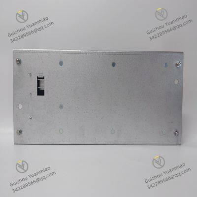
| Physical Specifications | - Dimensions (H × W × D): 120mm × 160mm × 80mm (compatible with UDC 920 system standard 3U rack, supporting DIN rail or panel mounting) - Weight: Approximately 0.5kg (including relays and connectors) - Indicator lamps: Each DI/DO channel is equipped with an LED status lamp (green = normal, red = fault/triggered); module power lamp (yellow) and communication lamp (blue) for on-site fault diagnosis |
Targeting the complex signal environment of industrial sites, the module ensures the stability of signal acquisition and output through hardware design and algorithm optimization:
Module parameters can be customized via ABB UDC 920 configuration software (e.g., Control Builder UDC):
A dual diagnostic mechanism (hardware + software) is built-in:
The front panel is equipped with 16 LED indicators (8 for DI channels, 4 for DO channels, 2 for power/communication, and 2 for faults). Operators can quickly determine channel status via indicator colors (e.g., steady green for DI channel = signal on; flashing red for DO channel = output fault).
3. Safety Interlock and Redundancy DesignIt meets the safety control requirements of industrial scenarios and supports risk prevention for critical links:

Send Inquiry to This Supplier

* Email
Want the best price?
Post an RFQ now!

1Yr
Business Type
Trading Company
Year Established
2014
Factory Size
1,000-3,000 square meters
Product Certifications
SA8000
You May Also Like
-
ABB 500AIM02 1MRB150022R001 Controller ModuleNegotiableMOQ: 1 Piece
-
ABB 500BIM01 1MRB150024R00026 Bus Interface ModuleNegotiableMOQ: 1 Piece
-
ABB 3BHE023784R1023 Controller ModuleNegotiableMOQ: 1 Piece
-
ABB PPD513A0E-110110 3BHE039724R0E41 AC 800PEC Controller ModuleNegotiableMOQ: 1 Piece
-
ABB PFV0-102 Versatile Programmable Logic Controller PFV0102NegotiableMOQ: 1 Piece
-
ABB XVC768116 3BHB007211R116 Control InverterNegotiableMOQ: 1 Piece
-
ABB 560PSU02 1KGT011900R0001 Power Supply Unit ModuleNegotiableMOQ: 1 Piece
-
ABB PM645B 3BSE010535R1 Processor ModuleNegotiableMOQ: 1 Piece
-
ABB LD 810HSE EX Fieldbus Linking DeviceNegotiableMOQ: 1 Piece
-
ABB GRID BREAKER UNIT GBU72 3BHB030310R0001NegotiableMOQ: 1 Piece


