








 Contact Platform Support
 Help Center
Home > Electrical & Electronics > Electrical Control System > HONEYWELL TK-PRR021 51309288-275 REDUNDANCY MODULE
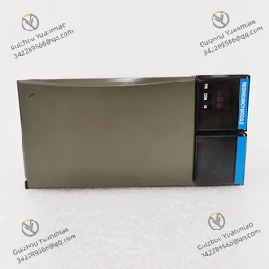
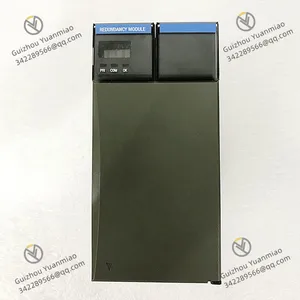
HONEYWELL TK-PRR021 51309288-275 REDUNDANCY MODULE



Negotiable
MOQ: 1 Piece (Price negotiable depending on order volume and customization)
Key Specifications
Get Latest Price
Material:
Other, Global universal model
Certification:
CE
Function:
Other, Global universal model

Payment & Shipping
Payment Methods:


Port of Shipment:
guizhou
Delivery Detail:
Delivery time depends on order quantity.
Related Products
-
 Honeywell TK-PRS021 51404305-275 Control Processor ModuleNegotiableMOQ: 1 Piece
 -
Honeywell SC-UCMX02 Non-redundant ControllerNegotiableMOQ: 1 Piece
-
Honeywell 51307198-276 Digital Output ModuleNegotiableMOQ: 1 Piece
-
Honeywell CC-PUIO01 24-Point Universal Input/Output (I/O) ModuleNegotiableMOQ: 1 Piece
-
Honeywell 51454205-175 Universal I/O ModuleNegotiableMOQ: 1 Piece
Material
Other, Global universal model
Certification
CE
Function
Other, Global universal model
Condition
New
Task
Other, Global universal model
Mathematical Model
Other, Global universal model
Signal
Other, Global universal model
Customized
Non-Customized
Structure
Other, Global universal model
The HONEYWELL TK-PRR021 (part number: 51309288-275) is a core redundancy module under Honeywell’s Experion PKS (Process Knowledge System). Specifically designed for the C200 controller, its core positioning is to "ensure the uninterrupted operation of industrial control systems under extreme working conditions through hardware redundancy and intelligent failover". It is designed in strict compliance with industrial-grade high-reliability standards and is widely used in critical process fields with "zero tolerance for system downtime" such as petrochemicals, oil and gas extraction, and thermal power generation. It serves as the core hardware carrier for Honeywell to achieve "fault-tolerant control".
Honeywell’s industrial control module models and part numbers follow the logic of "function classification + hardware version + adapted system". The meanings of TK-PRR021 and 51309288-275 are broken down as follows:
As a supporting module for the C200 controller, the physical design of the TK-PRR021 is strictly adapted to Honeywell’s standard I/O rack. The specific parameters are as follows:
| Item | Specification Details |
|---|---|
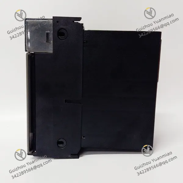
| Dimensions | 178mm (length) × 102mm (width) × 38mm (height), conforming to the "2-slot module" size standard of Honeywell’s C200 series. It occupies 2 consecutive slots in the C200 I/O rack (slot spacing: 32mm); |
| Weight | Approximately 0.48kg (including housing, circuit board, and lithium battery). It adopts a die-cast aluminum alloy housing (with anodized surface treatment), featuring both impact resistance and electromagnetic shielding capabilities; |
| Installation Method | Rail-mounted snap-in installation, locked to the rack card slot via spring snaps on both sides of the module. It supports "hot swapping" (in compliance with IEC 61326-1 standard), allowing replacement without powering off the system; |
| Status Indicators | 6 LED indicators (front panel layout), corresponding to: • Main processor status (green = running, red = fault, yellow = synchronizing); • Standby processor status (green = ready, red = fault, yellow = synchronizing); • Power status (green = dual-power supply normal, yellow = single-power supply, red = no power supply); • Battery status (green = sufficient power, yellow = low power, red = battery fault); |
| Interface Layout | Rear panel interfaces: • 2-way 24V DC power input (terminal type, supporting redundant power supply with reverse connection protection); • 1-way RS-485 communication interface (for data synchronization between main and standby modules); • 1-way test interface (BNC type, for manually triggering redundancy switchover tests); • 1-way battery replacement interface (snap-in type, allowing lithium battery replacement without disassembling the module); |
The electrical design of the TK-PRR021 focuses on "redundant reliability", supporting dual-power input and backup power supply. The specific parameters are as follows:
| Parameter Category | Specification Details |
|---|---|
| Power Requirements | • Main power supply: 24V DC ±10% (input current: 0.09A @ 24V DC), supporting dual-power input (mutual backup, switchover time • Internal core power supply: +5V DC ±5% (output current: 1.5A, for powering main and standby processors), +3.3V DC ±5% (output current: 1.0A, for powering communication and diagnosis circuits), +1.2V DC ±5% (output current: 0.007A, for powering clock chips); |
| Battery Backup | • Built-in lithium battery: CR2477 lithium-manganese battery (3V, capacity: 500mAh), non-rechargeable and replaceable independently. It maintains data caching of main and standby modules for 144 hours (at 25℃) after power failure; • Expansion support: Can be externally connected to Honeywell’s BEM (Battery Expansion Module, part number: 51309290-100) to implement rechargeable lithium battery pack backup, extending the battery life to 120 hours (supporting 500 charge-discharge cycles); |
| Power Consumption | Total power consumption ≤ 15W during normal operation (dual-power supply + battery standby), and instantaneous power consumption ≤ 20W during failover (duration |
| Insulation and Anti-interference | • Insulation resistance: ≥100MΩ (tested with 500V DC, between power supply and signal terminals); • Surge resistance: Compliant with IEC 61000-4-5 standard, the power supply terminal can withstand a 2kV (8/20μs) surge; • Electromagnetic Compatibility (EMC): Radiation disturbance complies with EN 55011 Class A, and anti-interference complies with EN 61000-6-2 (industrial environment); |
As the core indicator of a redundancy module, the failover and data synchronization capabilities of the TK-PRR021 directly determine system reliability. The specific parameters are as follows:
| Performance Indicator | Specification Details |
|---|---|
| Redundancy Architecture | Adopts a "1+1 hot standby" architecture, i.e., 1 active processor + 1 standby processor. Both operate with real-time synchronization, and the standby processor is in a "hot standby" state (rather than cold backup); |
| Failover Time | When the active processor fails (e.g., CPU abnormality, communication interruption), the standby processor automatically switches to the active state. The switchover time ≤ 10ms (from fault detection to the standby processor taking over control), which is much lower than the "minimum interruption threshold" allowed in industrial processes (usually 50ms), ensuring no loss of control commands; |
| Data Synchronization Speed | The main and standby modules achieve data synchronization through the internal RS-485 bus, with a synchronization cycle ≤ 1ms. The synchronized content includes control logic programs, I/O point statuses, PID parameters, alarm records, etc., with a synchronization error |
| Fault Detection Range | Built-in hardware-level fault detection circuit, capable of detecting the following fault types: • Active processor CPU faults (e.g., program crash, register abnormality); • Power supply faults (main power interruption, voltage over-limit); • Communication faults (communication interruption with I/O modules and upper computers); • Memory faults (RAM data error, ROM verification failure); |
| Switchover Trigger Modes | Supports 3 trigger modes: • Automatic trigger: Automatic switchover after the hardware detects a fault; • Manual trigger: Manual trigger of switchover via the front-panel "TEST" button or upper computer software (Experion Operator Station) (for regular testing); • Remote trigger: Sending switchover commands via the Modbus protocol (for remote maintenance); |
In response to harsh environments in industrial sites (high temperature, vibration, high humidity), the environmental adaptability parameters of the TK-PRR021 are as follows:
| Environmental Parameter | Specification Details |
|---|---|
| Operating Temperature | -40℃ ~ +70℃ (wide-temperature design, adapted for outdoor cabinets in cold regions and high-temperature chemical workshops). When the temperature exceeds this range, a "temperature alarm" is triggered, but the module can still maintain operation (the range of -45℃ ~ +75℃ is the "derated operation zone"); |
| Storage Temperature | -55℃ ~ +85℃ (meeting long-term inventory or transportation requirements); |
| Relative Humidity | 5% ~ 95% RH (non-condensing). The PCB board adopts IPC-CC-830 Class 3 conformal coating (acrylic coating, thickness: 50μm) to prevent erosion by moisture and oil; |
| Vibration and Shock | • Vibration: Compliant with IEC 60068-2-6 standard, acceleration of 2g (sinusoidal vibration) at 5-150Hz, and acceleration of 5g at 150-2000Hz; • Shock: Compliant with IEC 60068-2-27 standard, acceleration of 10g (11ms half-sine wave, non-operating state) and acceleration of 5g (operating state); |
III. Core Functions & Technical Advantages1. Intelligent Redundancy Control (From "Passive Backup" to "Active Fault Tolerance")The TK-PRR021 is not a simple "active-standby switcher" but achieves "full-link fault tolerance" through hardware-software collaboration. Its core functions include:
To cope with "sudden faults" in industrial sites (such as power surges and electromagnetic interference), the TK-PRR021 has multiple protections at the hardware level:
The "maintenance efficiency" of industrial control systems directly affects production continuity. The TK-PRR021 fully considers maintenance needs in its design:
The TK-PRR021 is not an independent module but an "integral part" of Honeywell’s Experion PKS system. Its compatibility is reflected in:

Send Inquiry to This Supplier


Business Type
Trading Company
Year Established
2014
Factory Size
1,000-3,000 square meters
Product Certifications
SA8000
You May Also Like
-
HONEYWELL TC-ODK161 Digital AC Output ModuleNegotiableMOQ: 1 Piece
-
HONEYWELL TC-PRR021 C200 Redundancy ModuleNegotiableMOQ: 1 Piece
-
HONEYWELL TC-XXXXX1 Temperature Control ModuleNegotiableMOQ: 1 Piece
-
HONEYWELL TK-FPDXX2 Standard Power SupplyNegotiableMOQ: 1 Piece
-
HONEYWELL TC-PRS021 Control Processor ModuleNegotiableMOQ: 1 Piece
-
HONEYWELL MU-PDOX02 51304487-100 Digital Output ModuleNegotiableMOQ: 1 Piece
-
HONEYWELL MU-PSIM11 51304362-300 UCN Serial InterfaceNegotiableMOQ: 1 Piece
-
HONEYWELL 51304511-200 Modem Circuit BoardNegotiableMOQ: 1 Piece
-
HONEYWELL 51401437-301 Dual Channel Safety Relay ModuleNegotiableMOQ: 1 Piece
-
HONEYWELL 51401286-100 EPDG Interface CardNegotiableMOQ: 1 Piece


