Material
Other, Global universal model
Certification
CE
Function
Other, Global universal model
Condition
New
Task
Other, Global universal model
Mathematical Model
Other, Global universal model
Signal
Other, Global universal model
Customized
Non-Customized
Structure
Other, Global universal model
The GE DS200SDCCG1AEC is a core drive control board for General Electric (GE) Speedtronic Mark V/Mark VI series industrial drive control systems. It primarily undertakes functions such as closed-loop speed control, torque regulation, power distribution, and fault protection for motor/turbine drive systems, serving as the "control hub" that connects the main circuit of the drive system (e.g., frequency converter, inverter) to the upper-level control system. Its design strictly adheres to the requirements for high dynamic response, high reliability, and anti-interference capability in the industrial drive field. It is widely used in large-scale drive equipment across thermal power, metallurgy, oil and gas industries—such as gas turbine starter motors, rolling mill main drive motors, and high-voltage motors for pump stations—directly determining the operational accuracy, stability, and safety protection capability of the drive equipment.
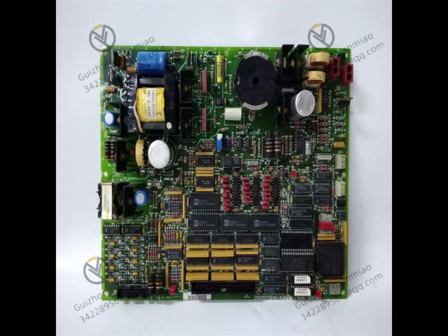
I. Basic Information and Core Positioning1. Interpretation of Model Identification
The model naming of GE drive control boards follows the logic of "system affiliation + function type + hardware version + configuration code". The specific meaning of DS200SDCCG1AEC is broken down as follows:
DS200: Prefix for the Mark V/Mark VI system hardware platform. Distinguished from the DS600 prefix of the later Mark VIe series, the DS200 series represents "classic drive control and signal processing modules". These modules are compatible with the Mark V system backplane bus and can be downwardly adapted to some Mark IV upgrade projects.
SDCC: Function code, where "S=Speed Control", "D=Drive", and "CC=Current Control". This clearly defines its core function as "speed-current dual closed-loop control of the drive system", while also integrating torque regulation and power limiting capabilities.
G1AEC: Hardware version and configuration details. "G1" denotes the 7th hardware revision (with letters corresponding to revision numbers: A=1, B=2... G=7), which features optimized chip computing speed and heat dissipation design compared to earlier versions. "A" indicates compatibility with AC drive systems (differentiated from the "B" version dedicated to DC drives). "E" signifies support for "energy feedback control" (suitable for variable-frequency speed regulation scenarios). "C" confirms the inclusion of a "redundant communication interface" to enhance data transmission reliability.
2. Core Application Scenarios
As the "control core" of the drive system, the DS200SDCCG1AEC is primarily adapted to GE’s medium- and high-voltage drive equipment. Typical application scenarios include:
Gas Turbine Starter Drive Control: During the gas turbine start-up phase, it controls the closed-loop speed regulation of the starter motor (e.g., 10kV high-voltage asynchronous motor). It drives the gas turbine rotor from a stationary state to the ignition speed (typically 800–1200 RPM) according to a preset curve (e.g., 50RPM/s speed rise rate). After successful ignition, it automatically switches to "idle speed control" and disconnects the starter motor.
Metallurgical Rolling Mill Main Drive Control: Adapted to rolling mill main motors (e.g., 6kV synchronous motors), it enables "speed-torque" dual-mode control. During rolling, it maintains constant rolling force in torque mode (to avoid deviations in steel plate thickness). During roll changes, it adjusts roller speed rapidly in speed mode, with a response time of ≤10ms.
High-Voltage Drive Control for Pump Stations/Fans: Used for variable-frequency drive control of large pump stations (e.g., urban water supply high-voltage pumps) and power plant induced draft fans. It supports "PID speed regulation" (automatically adjusting motor speed based on pipeline pressure/airflow demands) and is equipped with "overload limiting" (preventing motor burnout due to overcurrent) and "undervoltage protection" (stabilizing output during grid fluctuations).
Industrial Compressor Drive Control: Adapted to the variable-frequency drive systems of screw or centrifugal compressors, it maintains the compressor’s discharge pressure at the set value (e.g., 0.8MPa) through "speed-pressure" closed-loop control, with a deviation of ≤±0.02MPa. It also suppresses speed oscillations caused by load fluctuations (e.g., anti-disturbance control during sudden airflow changes).

II. Key Technical Parameters1. Control Performance Parameters
2. Electrical and Communication Parameters
3. Environmental and Physical Parameters

III. Core Functions and Technical Characteristics1. Speed-Current Dual Closed-Loop Control
As the core function of drive control, the module achieves high-precision speed regulation through "outer speed loop control + inner current loop control", with the following specific logic:
Speed Loop Control: Receives the speed setpoint (e.g., 1500 RPM) from the upper-level computer and actual speed feedback from the motor encoder. It calculates the "current setpoint" (e.g., 500A) via a PI regulator and superimposes "speed feedforward compensation" (adjusting current in advance based on the speed change rate to reduce overshoot). For example, when the motor load suddenly increases, the speed loop quickly increases the current setpoint to prevent speed drop, with a steady-state recovery time of ≤30ms.
Current Loop Control: Collects the three-phase current output by the frequency converter (via current transformers and Hall sensors) and compares it with the "current setpoint" output by the speed loop. It quickly adjusts the frequency converter’s trigger pulses (e.g., IGBT conduction angle) via a P regulator (proportional regulation) to stabilize the actual current at the setpoint, suppressing current fluctuations (e.g., current surges caused by grid voltage fluctuations).
Control Mode Switching: Supports "disturbance-free switching". For instance, when a rolling mill switches from "speed mode" to "torque mode", the module automatically uses the torque value corresponding to the current speed as the "initial torque setpoint". During switching, the output torque ripple is ≤3%, avoiding product defects caused by sudden changes in steel plate rolling force.
2. Drive Protection and Fault Handling
To address common fault risks in drive systems, the module integrates multi-level protection mechanisms to ensure equipment safety:
Overload Protection: Monitors motor current in real time. When the current exceeds 120% of the rated current, it triggers "current limiting" (maintaining 120% rated current output to prevent motor burnout due to overcurrent). If the current exceeds 150% of the rated current for 50ms, it immediately outputs a "shutdown command", cuts off the frequency converter’s power supply, and records the fault code (e.g., "F01-Motor Overload").
Undervoltage/Overvoltage Protection: Monitors grid voltage (e.g., 6kV bus voltage). When the voltage is lower than 85% of the rated value, it automatically reduces the motor speed (to lower power demand) to prevent the frequency converter from tripping due to undervoltage. When the voltage exceeds 115% of the rated value, it triggers "voltage limiting" to restrict the frequency converter’s output voltage and protect the IGBT module.
Fault Diagnosis and Recording: Features a built-in fault diagnosis circuit capable of detecting 12 types of common faults (e.g., encoder disconnection, current sensor fault, communication interruption). When a fault occurs:
It immediately turns on the red fault light and sends a "shutdown command" to the frequency converter.
It sends the fault code and key parameters at the time of the fault (e.g., speed, current, voltage during the fault) to the upper-level computer.
It stores the fault record in EEPROM (non-volatile), which can save the latest 20 fault records (including fault occurrence time and duration) to facilitate maintenance personnel in tracing the cause.
3. Energy Feedback and Energy-Saving Control
In variable-frequency speed regulation scenarios, the module supports the "energy feedback" function to achieve energy-efficient operation:
Feedback Control Logic: When the motor is in the "power generation state" (e.g., fan deceleration, elevator descent), the module detects an increase in the frequency converter’s DC bus voltage (e.g., exceeding 1100V). It automatically triggers the "energy feedback loop" (controlling the IGBT conduction direction) to feed the electricity generated by the motor back to the grid (requiring a supporting feedback transformer). It also maintains DC bus voltage stability (deviation ≤5%) through "voltage closed-loop control".
Energy-Saving Effect: Taking a fan as an example, when airflow demand drops to 50%, the motor speed can be reduced to 50% of the rated speed (per fluid mechanics laws, power is proportional to the cube of speed). Compared with "fixed-speed operation + damper adjustment", the energy-saving rate can reach 40%–60%.
Feedback Protection: If grid faults (e.g., voltage sag) prevent normal operation of the feedback channel, the module immediately switches to "dynamic braking" mode (consuming excess electricity via braking resistors) to prevent the DC bus voltage from becoming too high and damaging the frequency converter.
4. Redundancy and Communication Reliability Design
To meet the high reliability requirements of critical industrial scenarios (e.g., power plant drive systems), the module enhances redundancy design:
Communication Redundancy: Equipped with 2 CAN bus interfaces (main-standby redundancy). During normal operation, the main bus transmits data, and the standby bus synchronizes data in real time. If the main bus communication is interrupted (e.g., cable fault), the standby bus automatically takes over communication within ≤10ms without data loss.
Power Supply Redundancy: Supports dual power module supply (DC 5V main power + DC 5V standby power). If the main power supply fails, the standby power supply switches to provide power within ≤5ms, ensuring no interruption to the module’s control logic (avoiding drive system shutdown).
Hardware Redundancy: Core chips (e.g., DSP, current sampling chip) adopt a "hot backup" design. The main chip runs control logic, and the standby chip synchronizes data from the main chip in real time. If the main chip fails, the standby chip takes over control within ≤20ms to ensure continuous operation of the drive system (suitable for non-interruptible production scenarios, such as chemical reactor agitator drives).

IV. Compatible Equipment and Maintenance Guidelines1. Compatible Systems and Supporting Components
The DS200SDCCG1AEC must be used with dedicated components of the GE drive system and cannot be mixed with products from other brands:
Upper-Level Control Systems: GE Mark V/Mark VI turbine control system, GE DriveView drive monitoring system.
Frequency Converters/Inverters: GE medium- and high-voltage frequency converters (e.g., MV7000 series 6kV frequency converter, MV6000 series 10kV frequency converter).
Feedback Components: GE incremental encoders (e.g., 1024-line/2048-line, 5V differential signal output), GE Hall current sensors (e.g., CSNH series, output 4–20mA).
Power Modules: GE DS200PCCAG1A (DC 5V/±15V dual output), DS200PCCAG2A (redundant power module).
Configuration Software: GE DriveTool software (version ≥ V6.2), used for parameter configuration (e.g., PID gain, protection threshold), fault diagnosis, and control mode switching.