

Home > Electrical & Electronics > Electrical Control System > GE IS200TDBTH6ACD Input/Output Terminal Board

Negotiable
MOQ: 1 Piece (Price negotiable depending on order volume and customization)
Key Specifications
Get Latest Price
Material:
Other, Global universal model
Certification:
CE
Function:
Other, Global universal model
Payment & Shipping
Payment Methods:
Port of Shipment:
guizhou
Delivery Detail:
Delivery time depends on order quantity.
Related Products
-
 GE UR8FH UR-8FH Universal Relay ModuleNegotiableMOQ: 1 Piece
 -
GE PQMII-T20-C-A Power Quality MeterNegotiableMOQ: 1 Piece
-
GE IC8008SI228RD2-EE Safety Input ModuleNegotiableMOQ: 1 Piece
-
GE IS220PDIAH1A Discrete Contact Input Terminal BoardNegotiableMOQ: 1 Piece
-
GE DS200DCFBG2BNC MRP420024 Power Supply BoardNegotiableMOQ: 1 Piece
Material
Other, Global universal model
Certification
CE
Function
Other, Global universal model
Condition
New
Task
Other, Global universal model
Mathematical Model
Other, Global universal model
Signal
Other, Global universal model
Customized
Non-Customized
Structure
Other, Global universal model
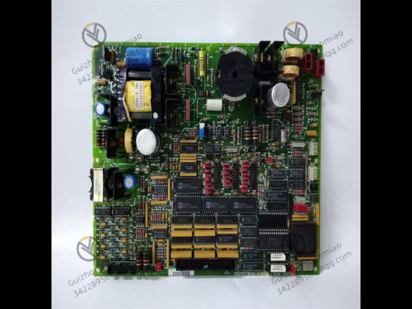
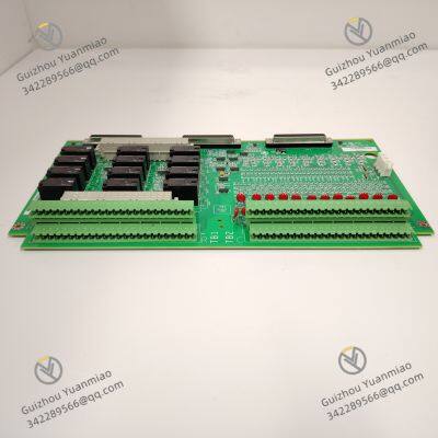
The GE IS200TDBTH6ACD is a specialized analog/digital hybrid Input/Output (I/O) terminal board engineered exclusively for GE’s Speedtronic Mark VIe and Mark VI control systems—core platforms deployed in power generation (gas/steam turbines), oil & gas processing, and heavy industrial operations. Unlike signal-processing modules that handle data computation, this terminal board acts as the "physical interface bridge" between field devices and the control system: it terminates wiring from on-site sensors/actuators, conditions raw signals to eliminate noise, and routes them to the Mark VIe/VI’s central I/O modules (e.g., IS200IBDHG1A for analog signals, IS200DBDHG1A for digital signals). Its design emphasizes industrial durability, signal reliability, and maintenance efficiency, making it essential for stable data transmission in harsh environments characterized by high vibration, electromagnetic interference (EMI), and extreme temperatures.
I. Basic Information & Core Positioning1. Model Naming InterpretationGE’s Mark VIe/VI terminal boards follow a standardized naming system to convey system compatibility, functionality, and configuration. The breakdown of IS200TDBTH6ACD is as follows:
As a hybrid I/O terminal board, the IS200TDBTH6ACD is tailored to scenarios requiring centralized, protected signal termination between field devices and the Mark VIe/VI control system. Key use cases include:
| Channel Type | Specifications |
|---|---|
| Analog Input (AI) Channels | - Quantity: 4 independent, configurable channels (CH1–CH4) via PCB jumpers. - Signal Types (selectable per channel): • Current input: 4–20mA DC (for pressure/flow sensors), input impedance ≤ 250Ω, accuracy ±0.1% of full scale (FS); • Voltage input: 0–10V DC (for position sensors), input impedance ≥ 100kΩ, accuracy ±0.2% FS; • RTD input: 3-wire Pt100 (for temperature), measurement range -200°C to +600°C, resolution 0.1°C. - Signal Conditioning: Each channel includes a 2nd-order RC low-pass filter (10Hz cutoff) to attenuate high-frequency noise (e.g., 50/60Hz power-line interference) by ≥40dB; dedicated 50Hz notch filter for RTD channels to eliminate power harmonics. |
| Digital I/O (DI/DO) Channels | - Quantity: 2 dual-function channels (CH5–CH6), configurable via DIP switches. - Signal Types (selectable per channel): • Digital Input (DI): Dry contact (NO/NC) or wet contact (24V DC), response time ≤1ms, input current ≤5mA @24V DC; • Digital Output (DO): Single-Pole Double-Throw (SPDT) relay, contact rating 2A/250V AC or 2A/30V DC (suitable for small actuators or alarm lights). - Protection: Each channel has a 2.5A fast-blow fuse (replaceable on PCB) for short-circuit protection; optical isolation (2500V AC, 1 minute) between digital channels and system bus to prevent ground loops. |
| Parameter Category | Specifications |
|---|---|
| Power Requirements | - Auxiliary Power: 24V DC ±10% (supplied by Mark VIe system auxiliary power modules, e.g., IS200PWRPG1A), power consumption ≤1.5W (no load) or ≤3W (full DO channel load). - Protection: Reverse polarity protection (via Schottky diodes) to prevent damage from incorrect power wiring. |
| Signal Isolation | - Analog Channels: Galvanic isolation (500V AC, 1 minute) between each AI channel and system ground to suppress common-mode noise. - Digital Channels: Optical isolation (2500V AC, 1 minute) between DI/DO channels and control system to isolate field-side EMI from core electronics. - Isolation Resistance: ≥100MΩ @500V DC (all isolated circuits). |
| Environmental Adaptability | - Operating Temperature: -40°C to +70°C (extended range via high-temperature capacitors and terminal blocks rated for -40°C to +85°C). - Relative Humidity: 5%–95% RH (non-condensing), with PCB conformal coating (IPC-CC-830 acrylic, 50μm thickness) to resist moisture and oil mist. - Vibration Resistance: 5g (10–2000Hz, IEC 60068-2-6) for sinusoidal vibration; 10g shock (11ms half-sine, IEC 60068-2-27). - EMC Compliance: EN 61000-6-2 (industrial immunity) – withstands 10V/m RF interference (80MHz–1GHz) and 4kV contact ESD. |
| Physical Dimensions | - Size (L × W × H): 180mm × 120mm × 30mm (fits standard 19-inch Mark VIe I/O racks, 1U height). - Terminal Blocks: Phoenix-style pluggable terminal blocks (3.81mm pitch), tool-less clamping (accepts 0.5–2.5mm² stranded wire). - Weight: ~0.3kg (including terminal blocks and mounting hardware). |
III. Core Functions & Technical Features1. Signal Conditioning & Noise SuppressionIndustrial environments generate significant electrical noise (e.g., from variable-frequency drives, high-voltage cables), which can distort sensor signals. The IS200TDBTH6ACD mitigates this via targeted hardware design:
The board supports on-site reconfiguration without software programming, adapting to diverse field device requirements:
The board minimizes downtime with features that simplify troubleshooting and replacement:
To withstand harsh operating conditions, the board incorporates durability-focused features:
IV. Compatible Systems & Maintenance Guidelines1. Compatible Hardware & SoftwareThe IS200TDBTH6ACD requires specific GE Mark VIe/VI components to function; it cannot be used with non-GE systems:
| Symptom | Possible Cause | Resolution |
|---|---|---|
| AI channel LED is red (out of range) | 1. Field sensor failure (e.g., broken Pt100); 2. Open signal cable; 3. Incorrect jumper setting. | 1. Test sensor with a multimeter (e.g., check Pt100 resistance); 2. Verify cable continuity; 3. Adjust jumper to match sensor type. |
| DO channel LED is yellow (fault) | 1. Short circuit in load (e.g., solenoid valve); 2. Blown 2.5A fuse; 3. Relay contact sticking. | 1. Disconnect load and test for shorts; 2. Replace fuse (F1/F2 on PCB); 3. Replace the terminal board if the relay is faulty. |
| All LEDs off (no power) | 1. Power module failure; 2. Reverse polarity; 3. Loose power terminal. | 1. Check IS200PWRPG1A output (22.8–26.4V DC); 2. Correct power wiring; 3. Tighten power terminals (1–2). |

Send Inquiry to This Supplier

* Email
Want the best price?
Post an RFQ now!

1Yr
Business Type
Trading Company
Year Established
2014
Factory Size
1,000-3,000 square meters
Product Certifications
SA8000
You May Also Like
-
GE IS420PPNGH1A Controller Gateway ModuleNegotiableMOQ: 1 Piece
-
GE UCSC H1 IS420UCSCH1A-F.V0.1-A UCSC ControllerNegotiableMOQ: 1 Piece
-
GE IC695CPE400-ABAB CPU ControllerNegotiableMOQ: 1 Piece
-
GE IS200EGPAG1BCA Exciter Gate Pulse Amplifier BoardNegotiableMOQ: 1 Piece
-
GE IS200EPSMG1AEC Exciter Power Supply ModuleNegotiableMOQ: 1 Piece
-
GE IS200PMCIH1AAA6BA00 Programmable Logic ControllerNegotiableMOQ: 1 Piece
-
GE IS200PDIOH1B Discrete I/O ModuleNegotiableMOQ: 1 Piece
-
GE IS200TSVCH1A Servo Input/Output Terminal BoardNegotiableMOQ: 1 Piece
-
GE IS200STCIH2A I/O Module Terminal BoardNegotiableMOQ: 1 Piece
-
GE IS200TRPAH2AHE Thermocouple Temperature Acquisition ModuleNegotiableMOQ: 1 Piece


