
- Guizhou Yuanmiao Automation Equipment Co., Ltd.
-
 1YrAnshun, Guizhou, China
 - Main products: ABB Triconex Foxboro LAM, Bentley Motorola Schneider, Kollmorgen HIMA ALSTOM, Reliance GE HONEYWELL NI、ICS
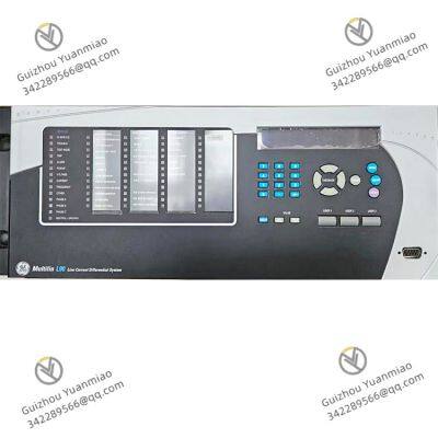


GE L90-W03-HKH-F8L-H6P-L6C-N6C-S6C-U6L-W7G Multilin L90 Protector
- guizhou
- T/T Other
You May Like
Product Details
| Material | Other, Global universal model | Certification | CE | |
| Function | Other, Global universal model | Condition | New | |
| Task | Other, Global universal model | Mathematical Model | Other, Global universal model | |
| Signal | Other, Global universal model | Customized | Non-Customized | |
| Structure | Other, Global universal model |
Product Description
GE 489 series Relay -02
 II. Hardware Structure and Functional Modules1. Core Control Unit2. Input/Output Modules3. Human-Machine Interface (HMI) and Communication Module
Company Profile
Main products: Covering globally renowned brands: Bently Nevada, Triconex, Woodward, Foxboro, Westinghouse, Reliance, Schneider Modicon, ABB, AB (Allen-Bradley), Motorola, GE Fanuc, Yaskawa, Bosch Rexroth Rexroth, ACSO, YOKOGAWA, Rexroth, NI, ICS Triplex, Kollmorgen, Mitsubishi, MOOG, Emerson, B&R B&r, SST, ALSTOM, KUKA EPRO, LAM HIMA dark Horse, HONEYWELL, prosoft, AMAT, SIEMENS, etc. The product categories include: DCS system accessories, robot system spare parts, large servo system spare parts, etc., which are widely used in power, chemical, metallurgy, intelligent manufacturing and other fields.
Contact Us
- Guizhou Yuanmiao Automation Equipment Co., Ltd.
- Contact nameyezi Chat Now
- AddressXixiu District, Anshun, Guizhou
Product Categories
New Products
-
ABB 086339-501 Digital Input Module
-
ABB 086348-001 PC Board
-
ABB 086444-005 Measurement Process Board
-
ABB RMU610 2VAA008425R1 Repeater Mounting Unit
-
ABB CHBX01L 2VAA008574R1 Compact Bus Extender
-
ABB CHBX01R 2VAA008575R1 Compact Bus Extender
-
ABB UFC921A 3BHE024856P106 Communication Module
-
ABB PP886 3BSE092980R1 Operation Panel
-
ABB SUE3000 1VCF750090R0804 Maintenance Exchange Unit
-
ABB SUE3000 1VCR007346 G0032 REF542plus HMI Unit
-
ABB GFD563A101 Interface Module
-
ABB 3BHE046836R0101 Interface Module
Popular Searches
Find Similar Products By Category
- Electrical & Electronics > Electrical Control System
Product Tags:
Guizhou Yuanmiao Automation Equipment Co., Ltd.

- Please Enter your Email Address
- Please enter the content for your inquiry.
We will find the most reliable suppliers for you according to your description.
Send Now-
 yezi
Hi there! Welcome to my shop. Let me know if you have any questions.
yezi
Hi there! Welcome to my shop. Let me know if you have any questions.
Your message has exceeded the limit.
- Contact supplier for lowest price
- Customized Request
- Request Sample
- Request Free Catalogs
Your message has exceeded the limit.
-
Purchase Quantity
-
*Sourcing Details
Your inquiry content must be between 10 to 5000 characters.
-
*Email
Please enter Your valid email address.
-
Mobile