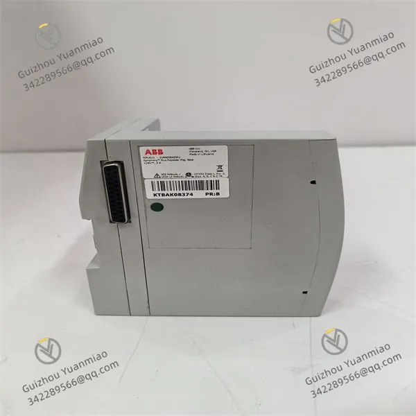
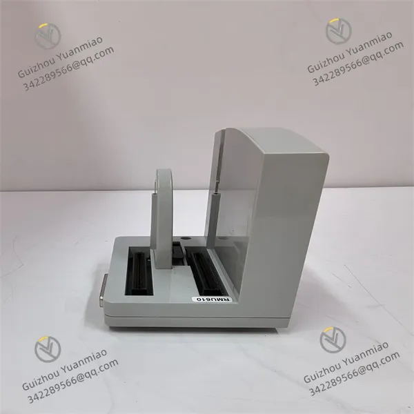
I. Product Overview
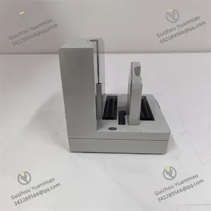
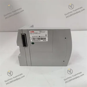
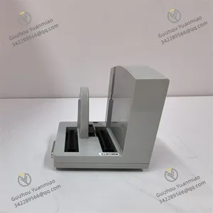
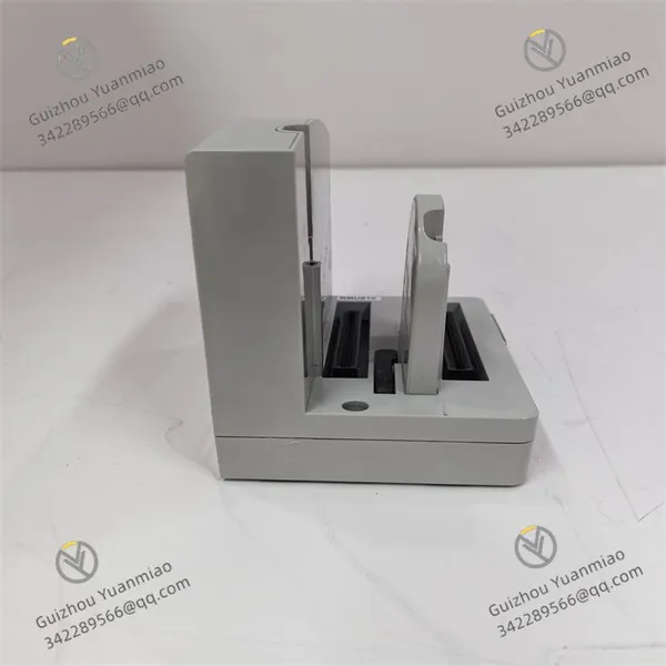
ABB RMU610 2VAA008425R1 is a meticulously engineered device that undertakes core control and protection tasks in the medium-voltage power distribution field. Developed and manufactured by ABB Group, a world-renowned industrial technology enterprise with profound technical accumulation and rich industry experience, its design closely aligns with the modern industrial demands for efficient and reliable power distribution systems.
The RMU610 features a compact and robust design with precisely calculated dimensions, enabling flexible adaptation to the internal space layout of various standard industrial control cabinets and greatly facilitating system integration. The device shell is made of high-quality fire-resistant and dust-proof materials, meeting relevant industrial standards for protection class. It can effectively resist dust, moisture, and accidental mechanical impacts in industrial environments, ensuring stable operation under harsh working conditions and extending the service life of the device. In terms of internal structure, it adopts an advanced multi-layer circuit board design with a compact and reasonable circuit layout and clear division of functional modules, which significantly improves the efficiency and stability of signal processing and data calculation. For heat dissipation, through the ingenious layout of heat sinks and the design of air circulation channels, the internal heat can be quickly dissipated, ensuring that the core chips and circuits remain within the appropriate operating temperature range when the device runs at high load for a long time, thus maintaining optimal performance.

II. Technical Parameters
(I) Electrical Parameters
Power Input: Supports dual 24V DC redundant input, featuring excellent power supply stability and reliability. The allowable voltage range is 18-32V DC, enabling adaptation to various complex power supply environments. The maximum input current per channel is 1A, and the power consumption is ≤15W under full-load operation, effectively reducing energy consumption and improving energy utilization efficiency.
Analog Input: Equipped with 8 analog input channels (expandable flexibly according to actual needs), fully supporting signal types including 0-10V DC voltage input and 4-20mA current input. The voltage input impedance is ≥10MΩ, and the current input impedance is ≤250Ω, ensuring the accuracy of signal transmission. It adopts a 16-bit A/D conversion resolution with a conversion accuracy of up to ±0.1% FS (Full Scale), which can accurately capture subtle changes in analog signals and provide high-precision data support for the system.
Analog Output: Provided with 4 analog output channels, the output signal types include 0-10V DC voltage output and 4-20mA current output. The voltage output load capacity is ≥10kΩ, the current output load capacity is ≤500Ω, and the output accuracy reaches ±0.1% FS, ensuring the stability and accuracy of the output signal and meeting the strict requirements for analog output in various industrial control scenarios.
Digital Input: Offers 16 digital input channels, compatible with dry contact, wet contact, and TTL level signals. The dry contact is powered by 24V DC internally, the input voltage range of the wet contact is 18-32V DC, and the TTL level supports 3.3V/5V. The input current of the dry contact is 2-5mA, and that of the wet contact is 5-10mA. The signal response time is extremely short (≤1ms), enabling rapid sensing of changes in digital signals, which is suitable for industrial application scenarios with high real-time requirements.
Digital Output: Configured with 8 digital output channels, adopting relay output mode (normally open/normally closed optional). The contact rating is 250V AC/5A and 30V DC/5A, and the output response time is ≤2ms. It can stably control operations such as the start and stop of external equipment, meeting various logic control needs in industrial automation control.
Communication Interfaces: Equipped with 1 fiber optic interface, supporting a transmission rate of up to 1Gbps, with single-mode/multi-mode options available. It meets the requirements for high-speed, long-distance, and anti-interference data transmission, and is particularly suitable for industrial on-site data communication in complex electromagnetic environments. Meanwhile, it is provided with 1 backplane bus interface with a transmission rate of 30MB/s, realizing efficient data interaction with other components in the system and ensuring the smooth operation and synergy of the entire system.
(II) Environmental and Reliability Parameters
Operating Temperature: The operating temperature range is -10℃ to 60℃, enabling adaptation to a wide range of environmental temperature conditions. It can operate stably whether in cold northern industrial sites or hot southern production workshops, ensuring the availability of the device in different regions and seasons.
Storage Temperature: The storage temperature range is -40℃ to 85℃. Even in extreme storage environments, the device can maintain good performance and reliability, providing guarantee for long-term storage and transportation of the device.
Relative Humidity: The relative humidity range is 5%-95% (non-condensing), strictly complying with the IEC 60068-2-38 humidity cycling standard. It effectively avoids equipment failures caused by humidity issues and ensures stable operation in humid industrial environments.
Protection Class: The module body has a protection class of IP20, suitable for installation in control cabinets, providing basic protection against dust and foreign object contact. At the same time, the protection class can be further improved by selecting an optional protective shell to meet the usage requirements in harsher environments. The connector part adopts an optional M12 waterproof connector with IP65 protection class, which effectively prevents moisture intrusion and ensures the reliability and stability of the connection.
Electromagnetic Compatibility: Fully complies with EN 55022 Class A (emission) and EN 55024 (immunity) standards, featuring excellent electromagnetic compatibility. The electrostatic discharge (ESD) protection capability reaches ±8kV (air discharge)/±4kV (contact discharge), and the electrical fast transient (EFT) protection capability is ±2kV. It can effectively resist complex electromagnetic interference in industrial sites, ensuring stable operation of the device and accurate data transmission.
Mechanical Vibration: Complies with the IEC 60068-2-6 standard, and can withstand mechanical vibration with an acceleration of 5g (sweep frequency test, 2 hours per axis) within the frequency range of 10-500Hz. It ensures the structural integrity and performance stability of the device in a vibrating environment, making it suitable for installation near equipment or locations with large vibrations.
Mechanical Shock: Meets the IEC 60068-2-27 standard, and can withstand mechanical shock of 15g and 11ms (half-sine wave, 3 times for each X/Y/Z axis). It has good shock resistance, which can effectively cope with accidental shocks that may occur during transportation, installation, and use, and ensure the safety of internal circuits and components of the device.
Mean Time Between Failures (MTBF): In accordance with the Telcordia standard, the MTBF is ≥160,000 hours in a 25℃ environment, demonstrating extremely high reliability. It reduces the frequency of equipment maintenance, lowers the risk of downtime in industrial production, and improves production efficiency.
(III) Communication and Configuration Parameters
Communication Protocols: The fiber optic interface supports the TCP/IP protocol, enabling convenient and efficient communication with many devices that support this protocol, and realizing fast data transmission and sharing. The backplane bus adopts ABB's proprietary communication protocol, which is deeply compatible with other components in the system, ensuring efficient and stable communication and guaranteeing the smooth operation of the entire system.
Data Upload Cycle: The data upload cycle can be flexibly set via software within the range of 10ms-1s according to the needs of actual application scenarios. It meets the differentiated requirements for data real-time performance in different industrial controls, and can be accurately adapted to both high-speed production line control with extremely high real-time requirements and conventional industrial monitoring scenarios with relatively low requirements for data update frequency.
Configuration Methods: Supports comprehensive and detailed configuration via ABB's proprietary Control Builder software, giving full play to the functional advantages of the device. At the same time, it is also compatible with third-party configuration software that meets industrial standards, providing users with diversified configuration options and facilitating flexible configuration by users according to their own usage habits and system architecture. In addition, it supports online parameter modification without shutdown operation, which greatly improves the convenience of system debugging and maintenance and reduces production losses caused by equipment shutdown.
Status Indication: The front of the module is equipped with multiple LED indicators for intuitive and clear display of the device's operating status. Among them, the power status indicator (PWR) is steadily green when the power supply is normal; the operation status indicator (RUN) blinks green when the device is in normal operation; the fault status indicator (ERR) is steadily red to warn of a fault. In addition, each channel is equipped with a corresponding LED indicator: green indicates that the channel signal is normal, and red indicates that the signal is abnormal. This allows users to quickly locate and troubleshoot problems and keep track of the device's operating status in a timely manner.
III. Functional Characteristics
(I) Accurate Measurement and Processing of Multiple Types of Signals
Analog Signal Processing
It has strong analog signal processing capabilities and can simultaneously access multiple types of analog sensor signals, such as millivolt-level signals output by temperature sensors, 4-20mA current signals from pressure sensors, and 0-5V voltage signals from liquid level sensors. The high-precision 16-bit A/D conversion module integrated inside can accurately convert analog signals into digital signals, with the conversion error controlled within an extremely small range. Taking the temperature monitoring of a reaction kettle in chemical production as an example, it can accurately capture the weak voltage changes output by the temperature sensor. Even if the temperature fluctuates by only 0.1℃, it can accurately measure and convert it into a digital quantity, providing precise temperature data for the control system and facilitating the accurate regulation of the production process. In view of the susceptibility of analog signals to interference, the module is carefully designed with multiple filtering circuits inside, including low-pass filtering, high-pass filtering, and band-pass filtering, which can be flexibly configured according to actual application scenarios. These circuits effectively filter out various interference signals generated by the complex electromagnetic environment in industrial sites, ensuring the accuracy and stability of measurement data.
Digital Signal Processing
It also performs excellently in digital signal processing. It supports the input of multiple types of digital signals, such as dry contact signals, wet contact signals, and TTL level signals. Relying on the high-speed digital signal acquisition circuit, it can quickly respond to changes in digital signals, with a signal response time of up to less than 1ms, which is particularly suitable for application scenarios that require highly accurate capture of signal changes, such as the monitoring of equipment start-stop status in high-speed production lines. For the logical processing of digital signals, the module has a built-in programmable logic unit. Users can program to perform logical operations (such as AND, OR, NOT) on the input digital signals according to actual control requirements, realizing complex logical control functions. For example, in an automated warehousing system, it can judge whether to execute the goods storage operation through logical operations based on multiple digital signals, such as the status of goods detection sensors, the operation status of motors, and the occupancy of storage locations, which greatly improves the automation and intelligence level of warehouse management.
(II) High-Speed and Stable Data Transmission
Fiber Optic Communication Interface
To meet the strict requirements for high-speed and reliable data transmission in industrial automation systems, the ABB RMU610 2VAA008425R1 is equipped with a high-performance fiber optic communication interface that supports direct fiber optic connection. Fiber optic communication has significant advantages such as high bandwidth, strong anti-interference ability, and long transmission distance. The data transmission rate of its fiber optic interface is as high as 1Gbps, which can quickly transmit a large amount of measurement data and processing results to the upper-level control system, meeting the needs of industrial application scenarios with extremely high real-time requirements. For example, in the blast furnace automation control system of a large iron and steel plant, a large amount of equipment operation parameters and process data need to be transmitted and processed quickly. The high-speed fiber optic communication interface of this module can ensure that the data is delivered in a timely and accurate manner, guaranteeing the efficient and stable operation of the production process. Since fiber optic communication is not affected by electromagnetic interference, it can reliably transmit data in industrial sites with strong electromagnetic environments, such as power substations and large motor-driven workshops, avoiding data packet loss and bit errors, and greatly improving the stability and reliability of data transmission.
Backplane Bus Communication
In addition to the fiber optic communication interface, the module also communicates with other components in the system through a high-speed backplane bus. The backplane bus adopts an advanced communication protocol with a data transmission rate of up to 30MB/s, enabling low-latency data interaction with the main controller, other I/O modules, and other devices. In industrial automation systems, data interaction between various components is frequent and has strict requirements on real-time performance. The high-speed backplane bus can ensure smooth communication between the ABB RMU610 2VAA008425R1 and other devices, realizing fast data sharing and collaborative work. For example, in the automation control system of an automobile manufacturing production line, through the backplane bus, the module can quickly transmit the collected equipment operation status, production process parameters, and other data to the main controller. After analysis and processing, the main controller can quickly issue control commands to the executive mechanisms through the backplane bus, realizing the efficient and automated operation of the production line and improving production efficiency and product quality.
(III) Comprehensive Fault Diagnosis and Self-Protection
Real-Time Fault Monitoring
It has a powerful real-time fault monitoring function and can conduct comprehensive and real-time monitoring of its own operating status. At the hardware level, through a variety of built-in sensors, it monitors key parameters such as power supply voltage, chip temperature, and operating current of each functional module in real time. Once it detects that the power supply voltage is outside the normal operating range (e.g., lower than 18V DC or higher than 32V DC), the chip temperature is too high (exceeding 70℃), or the operating current of a certain functional module is abnormal, the module will immediately trigger the corresponding fault alarm signal. At the software level, it uses advanced algorithms to conduct real-time analysis of input and output signals, enabling timely detection of abnormal situations such as signal loss and signal errors. For example, when it detects that an analog input signal remains unchanged for a long time or a digital input signal has abnormal jumps, the system will judge it as a signal fault and issue a corresponding fault prompt, providing an important basis for timely troubleshooting and fault resolution.
Fault Diagnosis and Reporting
When a fault occurs, the module can not only detect it in a timely manner but also has accurate fault diagnosis capabilities. Through the built-in fault diagnosis program, it can quickly locate the location and cause of the fault and generate a detailed fault report. The fault report contains rich information, such as the time when the fault occurred, the fault type (e.g., hardware fault, software fault, signal fault), the specific fault location (e.g., fault of the A/D conversion module of a certain channel, short circuit of a certain digital input pin), and the analysis of possible causes of the fault. This detailed fault information provides strong support for maintenance personnel to quickly troubleshoot and resolve faults, greatly shortening the fault troubleshooting time and improving the maintainability of the system. For example, in a petrochemical production device, when the ABB RMU610 2VAA008425R1 detects an abnormal signal in a certain channel, it can quickly diagnose that the signal loss is caused by a fault in the front-end sensor of that channel, and clearly indicate the location and fault type of the faulty sensor in the fault report. Maintenance personnel can quickly replace the faulty sensor according to the report to restore the normal operation of the system, reducing the production downtime and economic losses caused by the fault.
Self-Protection Mechanism
To prevent the further expansion of faults, the ABB RMU610 2VAA008425R1 has a built-in comprehensive self-protection mechanism. When a serious fault is detected, the module will automatically take corresponding protective measures, such as cutting off the circuits that may be affected by the fault to prevent the fault from spreading to other components. For some recoverable faults, the module will attempt to repair them automatically. For example, when it detects that the module operates abnormally due to an instantaneous fluctuation of the power supply voltage, the module will automatically activate the internal voltage stabilization circuit to adjust the voltage, and automatically resume normal operation after the voltage returns to normal. In terms of communication, when a fault is detected in the communication link, the module will automatically switch to the backup communication link (if available) to ensure the continuity of data transmission. For example, in the substation automation monitoring system of the power system, when a communication link fails due to external interference, the module can quickly switch to the backup fiber optic link to ensure the continuous upload of substation equipment operation data, avoiding monitoring blind spots caused by communication interruptions, ensuring the safe and stable operation of the power system, and providing a solid guarantee for the reliability of power supply.









 Contact Platform Support
 Help Center