Product Description
TRICONEX 8310 series module
The 3211S2 is a core safety - rated analog input module of Triconex, specifically designed for the Tricon Triple Modular Redundancy (TMR) Safety Instrumented System (SIS). As the "front - end analog signal acquisition unit" of the system, it can accurately collect continuously changing analog signals from the field (such as temperature, pressure, flow rate, etc.). Moreover, it achieves fault tolerance and signal reliability assurance through the TMR architecture. Widely used in fields with extremely high requirements for safety integrity like petrochemicals, nuclear power, natural gas, and pharmaceuticals, it provides precise analog input data for critical safety control scenarios such as Emergency Shutdown Systems (ESD), Fire and Gas Detection Systems (F&G), and process interlock protection.
 \
\
I. Basic Specification Parameters
The Triconex 3211S2 strictly adheres to the hardware design standards of Triconex safety systems, with "high redundancy, high protection, and high compliance" as its core, ensuring long-term stable operation in extreme industrial environments:
II. Core Electrical Performance and Signal Characteristics
As a safety-grade analog input module, the core competitiveness of the Triconex 3211S2 lies in three dimensions: signal acquisition accuracy, anti-interference capability, and redundant fault tolerance design, which can meet high-precision monitoring needs in complex industrial scenarios:
1. Input Channel and Signal Configuration
The module adopts a multi-channel differential input design, supporting a variety of industrial standard analog signals to adapt to different types of on-site sensors:
Number of Channels: 32 independent differential analog input channels (differential input effectively suppresses common-mode interference, with anti-interference capability more than 10 times higher than single-ended input);
Channel Grouping: Every 8 channels form a group, totaling 4 groups; each group can be independently configured with signal types (no need for uniform overall settings, improving wiring flexibility);
Input Signal Types: Only supports voltage-type analog signals; specific ranges can be configured via software:
Unipolar: 0~5V DC, 0~10V DC (suitable for signals starting from 0, such as those from pressure transmitters and flow sensors);
Bipolar: -5~+5V DC, -10~+10V DC (suitable for sensors requiring positive/negative range monitoring, such as temperature sensors and level sensors);
Input Impedance: ≥ 100kΩ (high input impedance avoids attenuation of the sensor output signal, ensuring acquisition accuracy);
Channel Isolation:
Inter-channel Isolation: Electrical isolation with an isolation voltage of ≥ 500V AC (50Hz/60Hz for 1 minute), preventing faults in one channel from affecting others;
Isolation Between Channels and System: Isolation voltage of ≥ 1000V AC (50Hz/60Hz for 1 minute), protecting the Tricon controller from on-site high-voltage interference.
2. Analog Signal Acquisition Accuracy Parameters
Accuracy is a core indicator of analog modules. The 3211S2 achieves industrial-grade high-precision acquisition through hardware calibration and software compensation:
3. Electrical Protection and Reliability Design
To address common electrical risks in industrial sites (overvoltage, short circuit, electromagnetic interference), the module integrates multiple protection mechanisms to ensure hardware safety and signal stability:
Overvoltage Protection: All input channels support continuous overvoltage protection of 150V DC / 115V AC (when the on-site signal is abnormally overvoltage, the built-in varistor and zener diode quickly clamp the voltage to prevent damage to the module's internal circuits);
Short-Circuit Protection: Each channel is equipped with an independent electronic fuse (current limiting ≤ 100mA). If a channel is short-circuited (e.g., positive and negative poles are shorted due to incorrect wiring), the fuse immediately cuts off the current and automatically recovers after the short-circuit fault is eliminated—no manual replacement required;
Electromagnetic Compatibility (EMC) Protection:
Electrostatic Discharge (ESD) Resistance: ±15kV (air discharge), ±8kV (contact discharge) (compliant with IEC 61000-4-2, preventing module damage from human electrostatic discharge during maintenance);
Surge Interference Resistance: ±2kV (power port), ±1kV (signal port) (compliant with IEC 61000-4-5, withstanding voltage surges caused by grid lightning strikes or equipment start/stop);
Radio Frequency Interference (RFI) Resistance: 10V/m (80MHz~1GHz frequency range) (compliant with IEC 61000-4-3, ensuring stable operation near high-interference equipment such as frequency converters and welding machines);
Reliability Indicators:
Mean Time Between Failures (MTBF): Approximately 1,000,000 hours (based on Triconex accelerated life testing and the use of industrial-grade components; calculated at 8760 operating hours per year, this equals over 114 years of average fault-free operation);
Safe Failure Fraction (SFF): ≥ 90% (meets the hardware reliability requirements of SIL 3, ensuring the module does not cause safety system misoperation or failure when faulty);
Diagnostic Coverage (DC): ≥ 99% (the module can detect over 99% of internal hardware faults, such as A/D converter faults and isolation circuit faults).
III. Core Functions and TMR Working Principle1. Core Function Positioning
As the "analog signal acquisition core" of the Tricon safety system, the Triconex 3211S2 undertakes four key functions that directly determine the input reliability of the safety system:
Safety-Grade Analog Signal Acquisition
It acquires continuous analog signals output by on-site sensors—such as pressure transmitters (0~5V corresponding to 0~10MPa pressure), temperature sensors (-5~+5V corresponding to -50~+50°C temperature), and flow sensors (0~10V corresponding to 0~100m³/h flow). These analog signals are converted into digital quantities and transmitted to the controller, providing raw data for safety logic operations.
TMR Triple Modular Redundancy and Signal Voting
The module has three completely independent signal acquisition channels (Channels A, B, and C). The same analog signal is simultaneously acquired, converted, and processed by the three channels. Through a "two-out-of-three (2oo3)" voting logic:
If the acquisition results of at least two channels are consistent, the signal is determined to be valid and output;
If the results of all three channels are inconsistent, an internal module fault is determined, an alarm is triggered immediately, and a preset safe state (e.g., maintaining the valid signal from the previous cycle) is output to avoid signal distortion caused by a single point of failure.
Online Calibration and Drift Compensation
It supports online zero and range calibration via Triconex-specific software (e.g., Tricon Explorer) without disassembling the module or shutting down the system. The software automatically records zero drift data of the module after long-term use and performs real-time compensation through algorithms, ensuring acquisition accuracy always meets requirements (especially suitable for long-term operation in chemical, nuclear power, and other projects).
Comprehensive Diagnostics and Status Feedback
It continuously monitors the module's own status (power supply, A/D converter, isolation circuit, backplane communication) and input signal status (overvoltage, short circuit, signal loss). Diagnostic information is transmitted in real time to the Tricon controller and operation station via the system bus. Additionally, the front panel of the module is equipped with 8 LED indicators (power light, 3 redundant channel status lights, fault light, calibration light, communication light) to visually display the operating status (e.g., a steady red fault light indicates an internal module fault, while a flashing light indicates an abnormal channel signal).
2. TMR Architecture Working Principle (Signal Acquisition and Processing Flow)
The core advantage of the Triconex 3211S2 lies in its TMR triple modular redundancy design. Its complete working process is divided into 5 steps to ensure "zero error and high reliability" of signals:
Step 1: Signal Input and Isolation
Analog signals from on-site sensors (e.g., 0~5V DC pressure signals) are connected to the corresponding channels of the module via differential wiring. The signals first pass through a channel-level isolation circuit (optical or magnetic isolation), which cuts off the direct electrical connection between on-site equipment and the module's internal circuits, eliminating the impact of common-mode interference and ground potential differences.
Step 2: Triple Modular Parallel Acquisition
The isolated analog signals are simultaneously sent to three independent acquisition channels (A, B, and C) inside the module. Each channel is equipped with an independent operational amplifier (to amplify weak signals), a low-pass filter (to filter high-frequency noise), and a 14-bit A/D converter (to convert analog signals into digital quantities). The three acquisition circuits are completely independent with no shared components, avoiding the risk of "catastrophic failure" where one fault affects all.
Step 3: Digital Signal Preprocessing
The digital quantities output by the three A/D converters are preprocessed by their respective microprocessors, including error calibration (compensating for hardware errors based on factory calibration data), data filtering (eliminating random noise), and validity judgment (rejecting obviously abnormal digital values, such as those exceeding the range).
Step 4: "Two-Out-of-Three" Voting Logic
The main voting unit of the module receives the preprocessed digital signals from the three channels and performs real-time comparison:
If the deviation of the three signals is within the allowable range (e.g., ≤±0.05% FS), the average value of the three signals is taken as the final valid signal;
If the deviation of one signal exceeds the range (e.g., the deviation between Channel A and Channels B/C is ≥0.1% FS), Channel A's acquisition circuit is determined to be faulty, its signal is shielded, and the average value of Channels B and C is taken as the valid signal;
If the deviations of all three signals are excessive (e.g., the deviations between A&B, B&C, and A&C are all ≥0.1% FS), a severe internal module fault is determined. A preset safe signal (e.g., the last valid signal before the module lost power) is output, and a fault alarm is triggered simultaneously.
Step 5: Signal Transmission and Diagnostic Feedback
The final valid signal is transmitted to the Tricon controller (e.g., Triconex 4351B) via the Tricon system backplane bus to participate in safety logic operations (e.g., determining whether pressure exceeds the safety threshold and whether to trigger an emergency shutdown). At the same time, the voting unit uploads the status (normal/faulty) of the three channels and diagnostic information (e.g., faulty channel number, fault type) to the controller, facilitating display on the operation station and fault location by maintenance personnel.
IV. Application Scenarios and Compatibility1. Typical Application Industries and Specific Scenarios
With its SIL 3 safety rating and TMR redundancy design, the Triconex 3211S2 is mainly used in industrial scenarios with extremely high safety integrity requirements—especially those requiring continuous analog monitoring and safety interlock triggering:
Petrochemical and Refining Industry
Scenario 1: Reactor Pressure Monitoring and Interlock
It acquires the 0~10V DC analog signal from the pressure transmitter at the top of the reactor (corresponding to 0~20MPa pressure) and transmits it to the Tricon controller. When the pressure exceeds the 18MPa safety threshold, the controller triggers an Emergency Shutdown (ESD) through logical operations: closing the feed valve and opening the pressure relief valve to prevent the reactor from exploding due to overpressure. The module's differential input design resists strong electromagnetic interference from frequency converters and motors in chemical plants, ensuring accurate pressure signal acquisition.
Scenario 2: Distillation Column Temperature Monitoring
It connects to temperature sensor signals (–10~+10V DC corresponding to –50~+150°C) from each tray of the distillation column to monitor the internal temperature distribution in real time. If the temperature of a tray exceeds the process range (e.g., above 120°C), the controller adjusts the opening of the heating steam valve to avoid deterioration of distillation efficiency; if the temperature rises sharply (e.g., above 140°C), it immediately triggers a feed cutoff interlock for the column bottom to prevent overheating and decomposition of materials inside the column.
Nuclear Power Industry
Scenario: Reactor Coolant Level Monitoring
It acquires the level sensor signal from the reactor coolant system (0~5V DC corresponding to 0~10m level) and ensures uninterrupted level signal acquisition through TMR redundancy. When the level drops below the 2m safety lower limit (which may cause the reactor to run dry), the controller triggers the emergency water supply system; if the level continues to drop to 1m, it immediately activates the reactor emergency shutdown procedure. The module's high reliability (MTBF over 1 million hours) and radiation-resistant design (supported by some models) meet the long-term maintenance-free operation requirements of the nuclear power industry.
Natural Gas and Pipeline Transportation Industry
Scenario: Long-Distance Pipeline Pressure and Flow Monitoring
At the booster station of a natural gas long-distance pipeline, the 3211S2 acquires signals from pipeline pressure transmitters (0~5V corresponding to 0~10MPa) and flow sensors (0~10V corresponding to 0~500m³/h). When the pressure is below 3MPa (indicating a potential leak) or the flow changes abruptly (e.g., exceeding 600m³/h), the controller triggers the closure of the station's emergency shutoff valve and sends an alarm signal to the dispatch center. The module's overvoltage protection function

 1YrAnshun, Guizhou, China
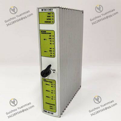


 yezi
Hi there! Welcome to my shop. Let me know if you have any questions.
yezi
Hi there! Welcome to my shop. Let me know if you have any questions.