Product Description
The GE IS200AEADH1AAA is a core peripheral hardware module under GE's Mark VIe series, categorized as an industrial-grade control system component. Primarily designed for wind power generation, industrial process control, and similar scenarios, it is responsible for the distribution, transfer, and reliable transmission of input/output (I/O) signals. Serving as a critical intermediate unit, it ensures stable signal interaction between the control system and on-site equipment. The following provides a detailed breakdown from dimensions including technical parameters, functional characteristics, application scenarios, and installation & maintenance, ensuring accuracy and comprehensiveness of information.
I. Basic Technical Parameters and Identification Information

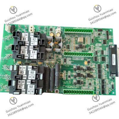
II. Hardware Structure and Appearance Design Details1. Core Structure of the Circuit Board
Substrate Material: Adopts FR-4 epoxy glass fiber substrate (1.6mm thick, compliant with IPC-6012 industrial board standards), featuring excellent insulation, heat resistance, and mechanical strength. It can withstand long-term vibration (vibration grade: 5-500Hz, acceleration 1.5g, compliant with IEC 60068-2-6 standard).
Component Layout: Employs a "signal zoning" design, separating power circuits, signal circuits, and grounding circuits to reduce electromagnetic interference (EMI):
Power Zone: Concentrates filter capacitors and voltage regulators, placed close to the power connector to minimize the impact of power noise on signals.
Signal Zone: Core components include signal transfer terminals, current-limiting resistors, and TVS transient voltage suppressor diodes (for surge protection), ensuring stable signal transmission.
Grounding Zone: Independently designed grounding pads, achieving "single-point grounding" through multi-path grounding to avoid ground loop interference.
2. Connector and Interface Configuration
As a "grid fork board", its core function of signal distribution relies on interfaces. The specific types and quantities of interfaces are as follows:
Main Signal Connector: 1 piece of 36-pin right-angle board-to-board connector (model: compatible with TE Connectivity 174945-2 or equivalent industrial connectors). It is used to connect with I/O master modules (e.g., IS200IOCCH1A) of the Mark VIe system for transmitting all I/O signals and power.
Branch Terminal Blocks: 3 sets of vertical pin terminal blocks (12 pins per set, 36 pins in total), adopting Phoenix Contact or equivalent industrial terminals (5.08mm pitch). Supporting "screw crimping" wiring, it is compatible with 16-24AWG (0.2-1.5mm²) copper conductors, and used to connect I/O signals of on-site sensors (e.g., temperature, pressure sensors) or actuators (e.g., relays, solenoid valves).
Auxiliary Interfaces: 1 piece of 4-pin pierce connector (for fast transfer of low-current signals such as status indicators and diagnostic signals) and 1 piece of 2-pin grounding terminal (for independent grounding to enhance anti-interference capability).
3. Installation and Fixing Methods
Installation Compatibility: Compatible with standard 19-inch racks of the Mark VIe system or "board guides" in customized control cabinets, supporting two installation methods: "vertical insertion" and "horizontal fixing".
Fixing Structure: The four corners of the circuit board are pre-drilled with 4 M3 threaded holes (3mm deep, pitch compliant with IEC 60917 standard), which can be fixed to the rack or mounting plate with screws to prevent displacement due to vibration during operation.
Anti-Misinsertion Design: The main connector adopts a "keyway guidance" structure, which can only be inserted when the interface is aligned in a specific direction, avoiding signal short circuits or module damage caused by incorrect installation.
III. Core Functions and Technical Characteristics1. Signal Distribution and Transfer Function
As a "grid fork board", its core role is to distribute the centralized signals of the I/O master module to multiple on-site devices and simultaneously collect feedback signals from on-site devices and transmit them back to the master module. Specific functions include:
Supports "1-in-multi-out" signal distribution: It can distribute 1 channel of control signal (e.g., relay trigger signal) output by the master module to up to 3 channels of on-site actuators, eliminating the need for additional signal splitters.
Supports "multi-in-1-out" signal collection: It can collect input signals from 3 channels of on-site sensors (e.g., 3 temperature sensors at different positions) and transmit them to 1 input channel of the master module, suitable for "redundant detection" or "multi-point monitoring" scenarios.
Signal integrity protection: On-board impedance-matching resistors (50Ω/75Ω optional, implemented via surface-mount resistors) and TVS transient voltage suppressor diodes (response time ≤ 1ns, breakdown voltage 30V) can suppress surge voltage and electromagnetic interference (EMI) introduced by on-site cables, preventing signal distortion or module burnout.
2. Reliability and Fault-Tolerance Design
To meet the high reliability requirements of industrial control scenarios, the module incorporates multiple fault-tolerance optimizations at the hardware level:
Conformal Coating Protection: The circuit board surface is covered with a uniform conformal coating (20-30μm thick), which can isolate dust, moisture, oil, and mild chemical corrosion (e.g., sulfides and nitrogen oxides in industrial environments), extending the module's service life in harsh operating environments (design life ≥ 10 years under standard working conditions).
Overcurrent/Overvoltage Protection: The power circuit is connected in series with a self-recovering fuse (PTC thermistor, rated current 1A). When the power supply current exceeds the threshold, it automatically disconnects and resumes conduction after the fault is eliminated, preventing burnout of core components due to power short circuits.
Thermal Design Optimization: Core components (e.g., connectors, filter capacitors) are all low-power models, and sufficient heat dissipation gaps are reserved during layout. The module can operate continuously at 70℃ without the need for additional cooling fans.
3. Compatibility and Expandability
System Compatibility: Only compatible with the GE Mark VIe control system, requiring matching with I/O master modules (e.g., IS200IOCCH1A, IS200IOCSH1A) and processor modules (e.g., IS200CPUH1A) of this series. It is incompatible with previous generations such as Mark V and Mark VI.
Signal Type Compatibility: Supports the transfer of analog signals (e.g., 4-20mA current signals, 0-10V voltage signals) and digital signals (e.g., dry contact signals, NPN/PNP switch signals). No distinction between signal types is required, and adaptive adjustment can be achieved through software configuration of the master module.
Expandability: A single I/O master module can connect up to 8 IS200AEADH1AAA fork boards. I/O points can be expanded through "daisy-chain" or "star" topology, meeting the multi-device control needs of large wind turbines or industrial plants.

IV. Application Scenarios and Typical Deployments
The module is originally designed to adapt to the "distributed I/O" architecture of the Mark VIe control system. Its core application scenarios focus on industrial fields with high requirements for reliability and anti-interference capabilities, as detailed below:
1. Wind Power Generation Field (Core Scenario)
Deployment Location: Inside the "nacelle control cabinet" or "tower base control cabinet" of wind turbines, close to on-site sensors/actuators (e.g., anemometers, pitch motors, hydraulic braking devices).
Specific Roles:
Transfers 4-20mA analog signals from temperature and vibration sensors in the nacelle to the tower base main controller for unit status monitoring.
Distributes pitch control signals (digital signals) output by the main controller to drive relays or frequency converters of pitch motors, realizing blade angle adjustment.
Collects dry contact signals from emergency stop buttons and safety chain switches in the nacelle, ensuring reliable transmission of emergency shutdown commands in critical situations.
2. Industrial Process Control Field (Auxiliary Scenario)
Applicable Industries: Petrochemical, natural gas processing, electric power (auxiliary systems for thermal power/nuclear power), pharmaceuticals, etc.
Typical Deployments:
In the Balance of Plant (BOP) system, it transfers I/O signals of auxiliary equipment such as water pumps, fans, and valves, enabling remote control and status feedback of auxiliary equipment.
In hazardous areas (e.g., Zone 2 explosion-proof areas in chemical workshops, requiring matching with explosion-proof cabinets), it transfers signals from gas detection sensors to ensure delay-free transmission of detection data to the Safety Instrumented System (SIS).
V. Product Status and Installation & Maintenance Instructions1. Product Production and Supply Status
2. Installation and Wiring Precautions
3. Fault Diagnosis and Maintenance
Common Faults and Troubleshooting:
No Signal Transmission: Check if the main connector is fully inserted and if the terminal block wiring is loose; use a multimeter to measure whether the power supply voltage is normal. If the voltage is 0, check if the self-recovering fuse is blown (after eliminating the short-circuit fault, wait 5-10 minutes for automatic recovery).
Signal Interference: Check if the shield layer is reliably grounded and if the cable is routed parallel to power cables; if analog signals fluctuate significantly, try replacing the impedance-matching resistor (must match the master module configuration).
Module Burnout: Mostly caused by overvoltage (e.g., power supply voltage exceeding 30V) or incorrect wiring (e.g., reversed positive and negative power supply poles). Core components (e.g., power chips, TVS diodes) need to be replaced. It is recommended to be handled by professional maintenance manufacturers; do not disassemble or solder by yourself.
Maintenance Support: The original factory provides paid maintenance services (cycle: approximately 2-4 weeks), while third-party maintenance manufacturers can offer faster turnaround times (approximately 1 week). After maintenance, the module performance must be verified through the "module self-test function" of the Mark VIe system (self-test pass standard: signal transmission delay ≤ 1ms, error rate ≤ 0.1%).
VI. Key Precautions
Compatibility Limitations: This module is only compatible with the Mark VIe system and cannot be used in control systems of other brands (e.g., Siemens, Rockwell), nor can it be mixed with GE's previous Mark V/VI series modules. Otherwise, signal incompatibility or system errors may occur.
Environmental Protection: Although it is equipped with a conformal coating, it cannot be directly exposed to outdoor rain, high-concentration dust, or corrosive gas environments. It must be installed in a sealed industrial control cabinet, and the cabinet should be equipped with cooling fans when the ambient temperature exceeds 50℃.
Spare Parts Management: Due to its discontinuation, it is recommended that users reserve 1-2 spare modules (new or refurbished) during system operation and maintenance to avoid system downtime caused by module faults. This is particularly crucial in scenarios such as wind power generation, which are "remote and difficult to maintain".
Basler Electric DECS125-15-B1 Digital Excitation Controller
BENTLY NEVADA 3701/55 ADAPT Condition Monitor
GE L90-W03-HKH-F8L-H6P-L6C-N6C-S6C-U6L-W7G Multilin L90 Protector
ABB PM863K01 3BSE088381R1 AC 800M Processor Unit Controller
ABB NGC8206 Natural Gas Chromatographs
Lam Research 810-068158-014 PCBA CIRCUIT BOARD
 II. Hardware Structure and Appearance Design Details1. Core Structure of the Circuit Board2. Connector and Interface Configuration

GE DS200TCDAH1BJE Mark V Digital I/O Board
ABB 086329-004 End Column Sensor Module
ABB 086370-001 Circuit Board
ABB 086339-501 Digital Input Module
ABB 086348-001 PC Board
ABB 086444-005 Measurement Process Board
ABB RMU610 2VAA008425R1 Repeater Mounting Unit
ABB CHBX01L 2VAA008574R1 Compact Bus Extender
ABB CHBX01R 2VAA008575R1 Compact Bus Extender
ABB UFC921A 3BHE024856P106 Communication Module
ABB PP886 3BSE092980R1 Operation Panel
ABB SUE3000 1VCF750090R0804 Maintenance Exchange Unit
 yezi
Hi there! Welcome to my shop. Let me know if you have any questions.


