Home > Electrical & Electronics > Electrical Control System > GE WESCOM D200 VME 0517-01230D Versatile And Reliable Module

GE WESCOM D200 VME 0517-01230D Versatile And Reliable Module
GE WESCOM D200 VME 0517-01230D Versatile And Reliable Module photo-1
GE WESCOM D200 VME 0517-01230D Versatile And Reliable Module photo-2
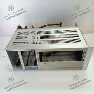
GE WESCOM D200 VME 0517-01230D Versatile And Reliable Module photo-3
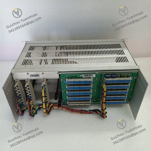
Negotiable MOQ: 1 Piece (Price negotiable depending on order volume and customization)
Key Specifications
Get Latest Price
Material:
Other, Global universal model
Condition:
Other, Global universal model
Task:
Other, Global universal model

Payment & Shipping
Payment Methods:
Port of Shipment:
China
Delivery Detail:
Delivery time depends on order quantity.
Material Other, Global universal model
Condition Other, Global universal model
Task Other, Global universal model
Mathematical Model Other, Global universal model
Signal Other, Global universal model
Customized Non-Customized
Structure Other, Global universal model
Operating Temperature -25℃~65℃
Relative Humidity 5% to 95% (non-condensing)
Storage Temperature -40℃~85℃

I. Product Overview


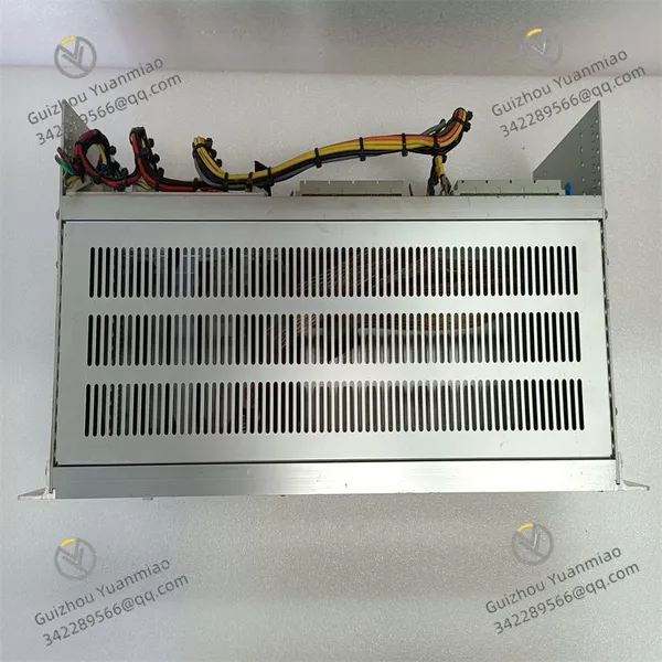
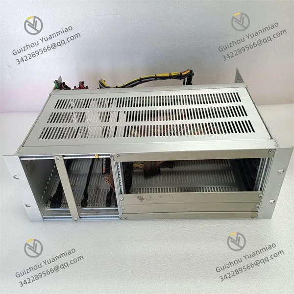
The GE WESCOM D200 VME 0517-01230D is an industrial control module based on the VME architecture and the D200 control system platform. It is specifically designed for medium-to-large industrial equipment in fields such as electric power, petrochemicals, and metallurgy (e.g., substation automation systems, large motor control systems, and process industry production lines). As the "control core expansion unit" of the D200 system, it undertakes the core responsibilities of centralized on-site signal processing, execution of control logic, and high-speed communication with other modules in the system. Meanwhile, it is compatible with the VME bus standard and can be flexibly integrated into the multi-slot rack of the D200 system, providing stable control capabilities and expansion space for industrial automation systems.


This module adopts a standard 3U VME industrial board form factor (approximately 100mm in height, 233mm in width, and 25mm in thickness), and is compatible with the dedicated VME rack of the GE WESCOM D200 system. It realizes data interaction and power supply with I/O modules and communication modules through the backplane bus. The surface of the module adopts an industrial-grade anti-interference layout; key chips (such as the CPU and communication controller) are equipped with metal shields, and the pin soldering process complies with the IPC-A-610 Class 3 industrial standard. It can withstand long-term high-load operation and complex electromagnetic environments (e.g., strong electromagnetic radiation in substations, interference from high-frequency inverters), and also features wide-temperature and moisture-proof properties. This allows it to operate stably in industrial sites with multiple interferences and wide temperature differences, ensuring the accurate execution of control commands and the security of data transmission.


WESCOM D200 VME 0517-01230D (1)


II. Technical Parameters


  1. Control and Signal Processing Parameters


Parameter Category Specific Specifications
Control Core 32-bit industrial-grade CPU, with a main frequency of ≥166MHz, supporting a Real-Time Operating System (RTOS), a control cycle of ≤2ms, and capable of parallel processing of over 1000 logic points
Input/Output Support Compatible with D200 system I/O expansion: Supports expansion of digital input/output (DI/DO) and analog input/output (AI/AO) modules. A single module can manage up to 32 channels of DI, 16 channels of DO, 16 channels of AI, and 8 channels of AO (requires connection to expanded I/O via VME bus)
Logic Operation Capability Supports programming in Ladder Diagram (LD) and Function Block Diagram (FBD), with built-in common control algorithms (e.g., PID regulation, interlock protection logic), and supports custom control strategies, with an operation accuracy of ±0.1%
Data Processing Capability Supports real-time data buffering (capacity ≥8MB), and can store historical data of key parameters within 1 hour (configurable sampling interval: 1-100ms), with a data loss rate of ≤0.001%


2. Electrical and Safety Features

  • VME Bus Compatibility: Complies with the VMEbus Rev. 3.0 standard, with a bus data transmission rate of 40MB/s, supporting 16-bit/32-bit data width. It enables seamless communication with other modules (e.g., communication modules, I/O modules) in the VME rack of the D200 system.

  • Isolation Protection: The isolation voltage between the input/output expansion interface and the backplane is ≥2.5kVrms, and the isolation voltage between channels is ≥2kVrms. It adopts photoelectric isolation technology to block common-mode interference (e.g., 500V common-mode voltage from inverters) and ground loops in industrial sites, with a signal transmission accuracy rate of 99.999%.

  • Overvoltage and Overcurrent Protection: The expanded I/O interface is equipped with ±30V DC overvoltage protection; digital output channels support external self-recovery fuses (rated current 3A); analog channels have a current limit of 30mA. This prevents module damage caused by on-site wiring errors or equipment failures.

  • Redundant Power Supply: Supports redundant power supply of +5V DC (for digital circuits) and ±12V DC (for analog circuits), with an allowable voltage fluctuation of ±5%. In case of a power failure, a system alarm is triggered via the VME bus to ensure the uninterrupted operation of control logic.


3. Environmental and Reliability Indicators

  • Operating Temperature: -25℃~65℃ (wide-temperature design), suitable for scenarios such as low-temperature outdoor control cabinets (e.g., substations in northern regions) and high-temperature industrial workshops (e.g., rolling mills in iron and steel plants).

  • Storage Temperature: -40℃~85℃, with no risk of component aging or pin corrosion during long-term storage.

  • Relative Humidity: 5%~95% (non-condensing). The board surface is coated with a moisture-proof coating with a thickness of ≥0.1mm, enabling stable operation in high-humidity and high-salt-fog environments (e.g., offshore platform power stations).

  • Mean Time Between Failures (MTBF): ≥100,000 hours. Key components (such as the CPU and bus controller) use industrial-grade long-life devices, reducing maintenance frequency and downtime risks.


4. Communication and Diagnosis Parameters

  • Communication Interfaces: 1 VME64x backplane interface (for communication with the D200 system rack), 1 RS485 interface (Modbus RTU protocol, for local debugging). It supports data interaction with the D200 system controller, with a response time of ≤50ms.

  • Diagnostic Functions: Supports VME bus communication fault detection, power failure detection, and open-circuit/short-circuit detection of expanded I/O channels. Fault information includes fault type and location (e.g., "AI Expansion Channel 2 Open"), which is uploaded to the D200 system monitoring interface in real-time via the bus.

  • Configuration Method: Supports remote configuration via GE WESCOM's dedicated configuration software (e.g., D200 Configuration Tool). It allows setting of control logic, I/O expansion parameters, and alarm thresholds. Configuration parameters are saved when power is off (with a built-in 64KB EEPROM), and supports backup and batch deployment of configuration files.


WESCOM D200 VME 0517-01230D (2)


III. Functional Features


1. VME Bus Compatibility and System Expansion

  • Flexible Integration Capability: Based on the VME bus standard, it can be directly inserted into the 3U VME rack of the GE WESCOM D200 system (supporting 16-slot/24-slot racks) without additional adaptive hardware. It can work in collaboration with the D200 system's communication modules (e.g., Ethernet modules) and I/O modules (e.g., analog input modules). A single rack can be configured with up to 4 such modules to meet large-scale control requirements.

  • Expanded I/O Management: By connecting to the distributed I/O modules of the D200 system via the VME bus, remote I/O expansion can be realized (maximum distance of 1000 meters, requiring fiber optic transmission). This adapts to signal acquisition and control in large industrial sites (e.g., cross-workshop motor control), reducing cable costs and signal attenuation.

  • Backward Compatibility: It is compatible with some VME modules of the GE WESCOM D20 system. When upgrading old D20 systems, this module can be directly replaced or added, protecting users' previous hardware investments and reducing system upgrade costs.


2. High-Reliability Control and Data Processing

  • Real-Time Control Assurance: The combination of a 32-bit CPU and RTOS ensures a control cycle of ≤2ms. It can quickly respond to changes in on-site signals (e.g., motor overload signals) and execute interlock protection logic (e.g., emergency shutdown) with a response time of ≤10ms, meeting the safety control requirements of industrial equipment.

  • Data Buffering and Backup: Equipped with an 8MB built-in data buffer, it can store key control parameters (e.g., voltage, current, temperature) in real-time. After a power outage, the buffered data is preserved by a backup battery (with a battery life of ≥72 hours), avoiding control misjudgment caused by data loss.

  • PID Regulation Optimization: Built-in adaptive PID algorithm supports online tuning of proportional (P), integral (I), and derivative (D) parameters. It can be used in closed-loop control scenarios such as motor speed regulation and valve opening control, with a regulation accuracy of ±0.5%, ensuring the stability of industrial process parameters.


3. Convenient Operation & Maintenance and Fault Localization

  • Software-Based Configuration: Control logic and I/O parameters can be configured visually via the D200 Configuration Tool software, eliminating the need for on-site hardware jumper modifications. Configuration updates can be completed within ≤5 minutes, reducing the on-site operation time of maintenance personnel.

  • Accurate Fault Feedback: The front panel of the module is equipped with LED indicators (PWR: power green, RUN: operation green, ERR: fault red, BUS: bus yellow). When a fault occurs, the ERR light turns on, and detailed fault information (including channel number and fault type) is uploaded via the bus. Maintenance personnel can quickly locate problems through the monitoring interface, reducing troubleshooting time by 50%.

  • Status Visualization: It supports real-time monitoring of the module's operating status (e.g., CPU load, bus communication rate, I/O channel status) via the D200 system operation station, allowing intuitive understanding of the module's working condition and facilitating preventive maintenance.


WESCOM D200 VME 0517-01230D (3)


IV. Installation and Operation & Maintenance


  1. Installation Specifications


(1) VME Rack Installation (D200 System Rack)

  • Tool Preparation: Phillips screwdriver (PH2), 4 M3 screws, ESD anti-static wristband (ground resistance ≤1MΩ), VME rack guide rails.

  • Anti-Static Operation: Wear the wristband and confirm proper grounding. Remove the module from its anti-static packaging, avoiding contact with the gold fingers and terminals.

  • Insertion and Fixing: Align the module with the 3U slot of the D200 VME rack, push it smoothly along the guide rails until the gold fingers at the bottom are fully in contact with the backplane. After hearing a "click" sound, fasten the sides of the module with M3 screws (torque: 1.2N・m). Ensure the front panel of the module is flush with the rack without tilting.

  • Bus Configuration: Use the configuration software of the D200 system controller to identify the newly added module (automatically reading the module serial number 0517-01230D), assign a VME bus address (which must not conflict with other modules in the rack), and complete the bus communication configuration.

(2) I/O Expansion Connection (Taking the Analog Input Module as an Example)

  • Connection of the Analog Input Module:

  1. After confirming a power outage, use a VME bus expansion cable to connect the "EXT I/O" interface of this module to the "VME IN" interface of the analog input module.

  2. After checking that the cable connection is secure, turn on the rack power. Activate the expanded I/O channels via the configuration software and confirm that the channel data acquisition is normal (e.g., the collected temperature signal matches that of the on-site sensor).


2. Daily Operation & Maintenance


(1) Regular Inspection (Once a Month)

  • Appearance Inspection: Check for damage to the module housing, oxidation of the gold fingers, and loose cable connections.

  • Status Verification: Check the front panel LED indicators (PWR/RUN lights should be on, ERR/BUS lights should be off). Use the D200 operation station to confirm that the module has no fault alarms, the CPU load is ≤70%, and there is no packet loss in bus communication.

  • Function Test: Issue test commands (e.g., controlling the output of a certain DO channel), observe whether the action of the on-site actuator is consistent with the feedback on the monitoring interface, and confirm that the control logic is normal.

(2) Troubleshooting

Fault Phenomenon Possible Causes Troubleshooting Measures
BUS light flashing, communication interrupted VME bus address conflict, loose bus cable Reconfigure the bus address, check and fasten the bus cable
ERR light on, "Power Fault" displayed on the monitor Unconnected redundant power supply, abnormal power voltage Check the power wiring, measure whether the voltage is within the allowable range of ±5%
No data in I/O channels Faulty expanded I/O module, poor cable contact Replace the expanded I/O module, re-plug the bus cable
Product Tags: WESCOM D200 , VME 0517-01230D

Send Inquiry to This Supplier

* Message
0/5000

Want the best price? Post an RFQ now!
Verified Business License
Business Type
Trading Company
Year Established
2014
Factory Size
1,000-3,000 square meters
Product Certifications
SA8000