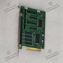
Material
Other, Global universal model
Condition
Other, Global universal model
Task
Other, Global universal model
Mathematical Model
Other, Global universal model
Signal
Other, Global universal model
Customized
Non-Customized
Structure
Other, Global universal model
Dimensions
140.72 mm × 113.54 mm
Operating Temperature
0°C to 55°C
Storage Temperature
-20°C to 70°C
NI PCI-6514Channel Configuration
Electrical Characteristics
Voltage Range: Both digital input and output voltage ranges are ±30 VDC.
Current Drive: Single-channel digital I/O current drive is 75 mA, maintaining 75 mA when all channels operate simultaneously.
Functional Features
Isolation: Eight groups of isolated channels, electrically isolated from each other to prevent cross-channel interference and enhance system stability/reliability.
Programmable Power-Up State: Users can configure initial output states via software to ensure safe operation when connecting industrial actuators (e.g., pumps, valves, motors, relays).
Watchdog Function: Equipped with a digital I/O watchdog that switches to a configurable safe output state in case of computer/application failures, enabling secure system recovery.
Input Filtering: Programmable input filters remove noise, spikes, etc., from input signals, debounce digital switches/relays, and improve input stability/accuracy.
Physical Specifications
Dimensions: Approximately 140.72 mm × 113.54 mm (5.54 in × 4.47 in).
Interface: Features a 100-pin high-density SCSI connector for external device connection.
Power Requirements: Requires +3.3 VDC (300 mA) and +5 VDC (250 mA) power supplies.
Operating Temperature: 0°C to 55°C.
Storage Temperature: -20°C to 70°C.

Working Principle of NI PCI-6514I. Functional Positioning
The NI PCI-6514 is a high-speed digital I/O data acquisition card designed for PCI bus, primarily used for digital signal interaction in industrial automation, testing systems, and research scenarios. Its core working principle focuses on digital signal I/O control, high-speed communication protocol processing, and electrical characteristic adaptation, with the hardware architecture decomposable into the following key components:
II. Digital I/O Channel Working Mechanism1. Electrical Characteristics & Signal Standards
Channel Configuration: 32 bidirectional digital I/O channels supporting TTL/CMOS levels (compatible with 0~5V signals), configurable as input, output, or tri-state modes.
Drive Capability: Maximum sink/source current of 40mA per channel, directly driving loads like relays, LEDs, or low-power solenoids.
Electrical Isolation: Partial channels (e.g., DI channels) support optical isolation (isolation voltage up to 2500 VRMS) for EMI resistance and device protection.
2. Input Signal Processing Flow
Signal Acquisition: External digital signals (e.g., switch quantities, encoder pulses) are connected to channels via interfaces, then level-converted to match internal logic levels.
Buffering & Filtering: Signals enter input buffer registers, with optional hardware filtering (e.g., debounce) to eliminate noise interference.
Data Reading: CPU or DMA controller reads register data via PCI bus, or triggers interrupts to notify system of data updates.
3. Output Signal Generation Flow
Data Writing: Software writes logic levels (0/1) to output registers via drivers.
Drive Amplification: Signals are amplified by drive circuits to meet external load requirements (e.g., driving relay coils).
Level Conversion: Outputs standard TTL/CMOS levels as configured, or converts to other levels (e.g., 24V industrial signals) via external circuits.
III. High-Speed Timing & Trigger Mechanisms1. Counter/Timer Functions
2. Triggering & Synchronization
Trigger Types: Supports digital triggering (TTL level edge/level), software triggering, and external clock synchronization, enabling collaboration with other devices (e.g., oscilloscopes, motion controllers).
Interrupt Handling: Sends interrupt requests to CPU via PCI bus during trigger events for real-time response (e.g., fast capture of Sudden outbreak signals).

IV. PCI Bus Communication & Data Transmission1. Bus Interface & Data Transfer Modes
Bus Specifications: 32-bit/33MHz PCI bus with theoretical bandwidth of 132MB/s, supporting DMA (Direct Memory Access) mode.
DMA Transmission: Enables CPU-independent data transfer between memory and acquisition card buffers, suitable for high-speed batch data interaction (e.g., real-time monitoring of massive digital I/O states).
2. Data Buffering & Flow Control
On-board FIFO (First-In-First-Out) buffers temporarily store I/O data to prevent loss during high-speed transmission.
Software can configure buffer size and overflow handling strategies (e.g., interrupt notification, data overwrite) via drivers.
V. Signal Conditioning & Compatibility Design1. Electrical Protection & Anti-Interference
Input channels integrate overvoltage protection circuits (e.g., TVS diodes) to prevent chip damage from external transient voltages (e.g., static electricity, surges).
Optically isolated channels block ground loop interference via optocouplers, suitable for strong electromagnetic industrial fields.
2. Interface & Expansion Compatibility
Supports NI standard signal conditioning platforms (e.g., SCB-68 terminal blocks) for external resistors, capacitors, etc., to implement signal voltage division, filtering, and other preprocessing.
Compatible with multi-card parallel expansion, achieving multi-device channel synchronous control via synchronization lines (e.g., distributed I/O systems).
VI. Software Drivers & Programming Interfaces1. Driver Layer Working Principle
Abstracts hardware operations via NI-DAQmx drivers, providing unified API interfaces to hide underlying register operation details.
Supports interrupt-driven and polling modes: Interrupt mode suits real-time response scenarios (e.g., external trigger events), while polling mode suits periodic data acquisition.
2. Programming & Configuration Flow
Initialization: Configures channel functions (I/O, isolation mode, etc.) via Measurement & Automation Explorer (MAX).
Programming Control: Calls driver functions using LabVIEW, Python, C++, etc., to implement data reading/writing, trigger setup, and timing control.
Real-time Monitoring: Driver layer provides status register query functions for diagnosing channel faults (e.g., overload, disconnection).
VII. Working Processes in Typical Application Scenarios1. Industrial Automation Control
2. Encoder Position Measurement
VIII. Technical Differences from Similar Products (Taking NI PCI-6525 as Example)
| Feature | NI PCI-6514 | NI PCI-6525 |
|---|
| Channel Count | 32 digital I/O (non-isolated) | 24 digital I/O (fully optical isolated) |
| Maximum Counting Frequency | 80 MHz | 40 MHz |
| Drive Current | 40 mA/channel | 50 mA/channel |
| Typical Scenarios | Laboratory testing, light industrial control | Harsh industrial fields, safety-isolated scenarios |