

Home > Electrical & Electronics > Electrical Control System > NI PXI-6527 185633D-01 Digital I/O Module
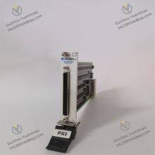
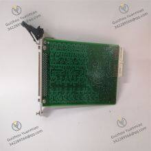
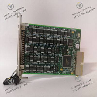
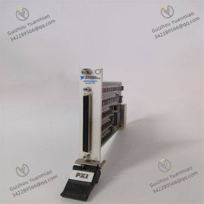
NI PXI-6527 185633D-01 Digital I/O Module


Negotiable
MOQ: 1 Piece (Price negotiable depending on order volume and customization)
Key Specifications
Get Latest Price
Material:
Other, Global universal model
Condition:
Other, Global universal model
Task:
Other, Global universal model
Payment & Shipping
Payment Methods:
Port of Shipment:
China
Delivery Detail:
Delivery time depends on order quantity.
Related Products
-
 NI PXI-6608 185745H-02 Timing and Synchronization ModuleNegotiableMOQ: 1 Piece
 -
NI PXI-6713 Analog Output ModuleNegotiableMOQ: 1 Piece
-
NI PXI-7344 Motion Control ModuleNegotiableMOQ: 1 Piece
-
NI PXI-8423 Serial Communication ModuleNegotiableMOQ: 1 Piece
-
CFP-AI-111 Analog Input Module NINegotiableMOQ: 1 Piece
Material
Other, Global universal model
Condition
Other, Global universal model
Task
Other, Global universal model
Mathematical Model
Other, Global universal model
Signal
Other, Global universal model
Customized
Non-Customized
Structure
Other, Global universal model
NI PXI-6527I. Product Positioning and Core Features
V. System Integration and Expansion Solutions1. Hardware Matching Recommendations2. Performance Optimization Measures

Send Inquiry to This Supplier

* Email
Want the best price?
Post an RFQ now!

1Yr
Business Type
Trading Company
Year Established
2014
Factory Size
1,000-3,000 square meters
Product Certifications
SA8000
You May Also Like
-
CFP-DO-403 Digital Output Module NINegotiableMOQ: 1 Piece
-
PXI-1033 PXI (PCI EXtensions for Instrumentation) Chassis NINegotiableMOQ: 1 Piece
-
SCXI-1001 Chassis NINegotiableMOQ: 1 Piece
-
32 Channel Thermocouple Amplifier Module SCXI-1102BNegotiableMOQ: 1 Piece
-
Voltage Input Module SCXI-1104CNegotiableMOQ: 1 Piece
-
6-channel Analog Output Module SCXI-1124NegotiableMOQ: 1 Piece
-
8-channel Differential Amplifier Module SCXI-1140NegotiableMOQ: 1 Piece
-
Optical Isolated Digital Input Module SCXI-1162HVNegotiableMOQ: 1 Piece
-
Terminal Block SCXI-1302NegotiableMOQ: 1 Piece
-
Terminal Block SCXI-1304NegotiableMOQ: 1 Piece


