Home > Electrical & Electronics > Electrical Control System > NI PXI-6713 Analog Output Module

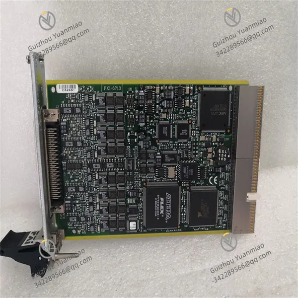
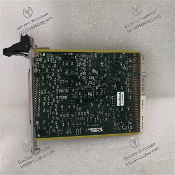
NI PXI-6713 Analog Output Module

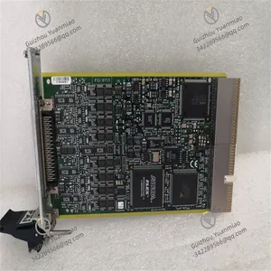
NI PXI-6713 Analog Output Module photo-1
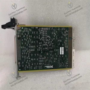
NI PXI-6713 Analog Output Module photo-2
Negotiable MOQ: 1 Piece (Price negotiable depending on order volume and customization)
Key Specifications
Get Latest Price
Material:
Other, Global universal model
Condition:
Other, Global universal model
Task:
Other, Global universal model

Payment & Shipping
Payment Methods:
Port of Shipment:
China
Delivery Detail:
Delivery time depends on order quantity.
Material Other, Global universal model
Condition Other, Global universal model
Task Other, Global universal model
Mathematical Model Other, Global universal model
Signal Other, Global universal model
Customized Non-Customized
Structure Other, Global universal model
Temperature 0℃~55℃
Humidity 5%~95% (non-condensing)
NI PXI-6713I. Product Positioning and Core Features
The NI PXI-6713 is a high-performance analog output module based on the PXI bus, specifically designed for high-precision voltage/current signal generation, dynamic waveform simulation, and closed-loop control systems. Its core features include:


  • Multi-Channel High-Precision Output: 16 independent analog output channels with 16-bit resolution, supporting ±10 V voltage or 0~20 mA/4~20 mA current output to meet precision signal conditioning requirements.

  • High-Speed Update Rate: Up to 1 MS/s per channel, supporting real-time dynamic waveform generation for applications such as high-frequency response testing and motor drive control.

  • Flexible Waveform Generation: Supports DC output, arbitrary waveforms (via onboard memory buffering), and scanned waveforms (linear/logarithmic scanning) to adapt to complex signal simulation needs.

  • Synchronization and Triggering Mechanisms: Compatible with PXI trigger buses, external triggers, and hardware synchronization, enabling collaborative operation with other modules (e.g., data acquisition cards, timing modules) for multi-system synchronized control.

II. Hardware Specifications and Technical Parameters
Parameter Category Specific Indicators
Output Channels 16 independent analog output channels with 16-bit DAC (Digital-to-Analog Converter)
Output Range - Voltage: ±10 V, 0~10 V, 0~5 V (configurable)
- Current: 0~20 mA, 4~20 mA (requires external load)
Resolution 16 bits (corresponding to voltage accuracy of ~0.153 mV @ ±10 V range)
Update Rate Up to 1 MS/s per channel; 160 kS/s for synchronized multi-channel output (all 16 channels)
Settling Time
Output Impedance - Voltage mode: - Current mode: 250 Ω (typical)
Triggering & Synchronization - Supports PXI trigger buses (TRG0~TRG7), external trigger input/output
- Compatible with NI synchronization clock (100 MHz)
Electrical Characteristics - Voltage output accuracy: ±0.025% FSR (Full Scale Range)
- Linearity: ±0.01% FSR
Operating Environment - Temperature: 0℃~55℃
- Humidity: 5%~95% (non-condensing)
Bus Compatibility PXI 2.2 standard, 32-bit/33 MHz PCI bus with maximum data transfer rate of 132 MB/s

PXI-6713 (2).jpg

III. Typical Application Scenarios1. Precision Signal Source and Test Systems
  • Scenario: Testing RF modules in communication devices requires generating high-precision IQ baseband signals to drive vector signal generators.

  • Implementation: Leverage 16-bit resolution and low-noise output characteristics to generate quadrature waveforms via LabVIEW programming, synchronously output to the RF front-end through dual channels to ensure signal distortion

2. Industrial Closed-Loop Control Systems
  • Scenario: Precision platform motion control in semiconductor lithography machines requires real-time voltage signals to drive servo motors for nanometer-level positioning.

  • Implementation: Receive position feedback data in real-time via 1 MS/s high-speed update rate, compute control values, and output analog voltages through the NI PXI-6713 to drive servo amplifiers, forming a closed-loop control (response time

3. Dynamic Waveform Simulation and Emulation
  • Scenario: Simulating dynamic sensor signals (e.g., engine speed, throttle position) in automotive ECU testing.

  • Implementation: Utilize the onboard 16 kB waveform buffer to pre-store dynamic waveforms such as acceleration/deceleration curves, and replay them in real-time via hardware triggers to simulate sensor outputs under real operating conditions.

IV. Software Support and Programming InterfacesDrivers and Development Tools
  • NI-DAQmx Driver: Compatible with platforms such as LabVIEW, Python, C++, and MATLAB, providing APIs for channel configuration, waveform generation, and trigger control.

  • NI MAX: Hardware configuration tool supporting output range calibration, channel mapping setup, and real-time monitoring of output status.

  • SignalExpress: Graphical test software enabling quick generation of DC/AC waveforms without programming, ideal for prototype verification.

LabVIEW Programming Example (Pseudocode)
plaintext
// Configure multi-channel DC output (control multiple solenoid valves) [Initialize Task] → Create 16-channel voltage output task with range set to 0~5 V   → Write DC value array [2.5, 0, 5, ...] to each channel (corresponding to solenoid valve states)   → Enable hardware trigger (rising edge of TRG0) to update all channels upon trigger   // Generate sine wave (test audio amplifier) → Configure Channel 0 for waveform output mode at 100 kS/s sampling rate   → Generate 1 kHz sine wave array (1024 points) and store in onboard buffer   → Enable loop playback mode, synchronize with external acquisition card (e.g., NI PXI-5122) via PXI clock   // Closed-loop control application (motor speed regulation) While (running) {     Read encoder feedback speed (via NI PXI-6259 acquisition card)       Calculate speed deviation and generate PID control value (-10~10 V)       Write control value to Channel 8 of NI PXI-6713 to drive motor controller       Delay 1 ms (ensure control loop frequency of 1 kHz) }

PXI-6713 (1).jpg

V. System Integration and Expansion SolutionsHardware Matching Recommendations
  • High-Precision Reference Source: Pair with the NI PXI-4130 power supply module to provide stable reference voltage for analog outputs, further enhancing output accuracy (ideal for metrology-grade testing).

  • Signal Conditioning: Use the NI SCB-68A terminal block supporting current/voltage mode conversion, filtering, and overload protection for industrial environments.

  • Multi-Module Synchronization: Collaborate with the NI PXI-6608 timing module to achieve nanosecond-level synchronization of multiple analog output cards via star trigger lines, suitable for multi-channel vibration table driving.

Performance Optimization Strategies
  • Anti-Interference Design: Use shielded cables for analog signal transmission and split ground planes (separate analog and digital grounds) to reduce EMI impact on output accuracy.

  • Real-Time Optimization: Employ DAQmx Streaming Mode with DMA direct memory access to reduce CPU load and ensure waveform stability at high update rates.

VI. Comparison with Similar Products
Model NI PXI-6713 NI PXI-6723 NI PXI-6733
Channels 16 channels 8 channels 4 channels
Resolution 16 bits 18 bits 20 bits
Max Update Rate 1 MS/s (per channel) 2.8 MS/s (per channel) 1 MS/s (per channel)
Output Range ±10 V, 0~20 mA, etc. ±10 V, ±5 V, etc. ±10 V, ±1 V, etc.
Core Advantage Balanced multi-channel performance Ultra-high resolution (precision testing) Ultra-low noise (sensor simulation)
Applications Industrial control, multi-channel testing Semiconductor parameter analysis, metrology calibration Medical device signal simulation, audio testing
Product Tags: PXI-6713

Send Inquiry to This Supplier

* Message
0/5000

Want the best price? Post an RFQ now!
Verified Business License
Business Type
Trading Company
Year Established
2014
Factory Size
1,000-3,000 square meters
Product Certifications
SA8000