Home > Electrical & Electronics > Electrical Control System > Foxboro FBM202 P0926EQ 8-Channel Isolated Input Module

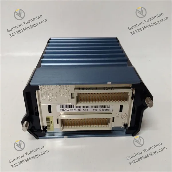
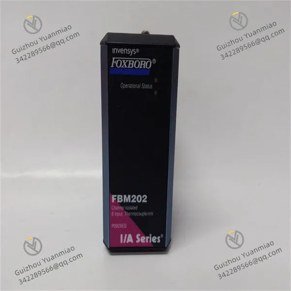
Foxboro FBM202 P0926EQ 8-Channel Isolated Input Module
Foxboro FBM202 P0926EQ 8-Channel Isolated Input Module photo-1
Foxboro FBM202 P0926EQ 8-Channel Isolated Input Module photo-2
Negotiable MOQ: 1 Piece (Price negotiable depending on order volume and customization)
Key Specifications
Get Latest Price
Material:
Other, Global universal model
Condition:
Other, Global universal model
Task:
Other, Global universal model

Payment & Shipping
Payment Methods:
Port of Shipment:
China
Delivery Detail:
Delivery time depends on order quantity.
Material Other, Global universal model
Condition Other, Global universal model
Task Other, Global universal model
Mathematical Model Other, Global universal model
Signal Other, Global universal model
Customized Non-Customized
Structure Other, Global universal model
Dimensions 10cm×10cm×5cm
Weight 0.5kg
Foxboro FBM202 P0926EQBasic Information
  • Origin: United States.

  • Weight: Approximately 0.4kg.

  • Dimensions: Approximately 10cm×10cm×5cm.

Functional Characteristics
  • Channel Configuration: Equipped with 8 thermocouple input channels and 1 isolated Resistance Temperature Detector (RTD) reference junction compensation channel, used for measuring thermocouple signals across different temperature ranges and providing thermocouple burnout detection.

  • Signal Isolation: Each input channel achieves current isolation from other channels and ground, with an isolation voltage up to 2500Vrms, effectively resisting interference and suitable for harsh industrial environments.

  • High-Precision Measurement: Adopts Σ-Δ data conversion technology for high-precision measurement. The millivolt input accuracy is ±0.03% of the full scale (±24μV at 25°C), and the thermocouple accuracy is ±0.25°C.

  • Wide Input Range: The input range is -10.5 to +69.5mV dc, corresponding to 0 to 64000 raw counts. The full scale is 71.419mV corresponding to 65535 raw counts. Additionally, it can measure thermocouple signals from -400°C to 1700°C.

  • Multiple Configuration Options: Executes analog input applications, providing configurable options for integration time and rate-of-change limits.

Working Principle
The module collects thermocouple or millivolt electrical signals from field sensors, processes the signals through internal signal conditioning circuits (amplification, filtering, etc.), and converts analog signals to digital signals using high-precision analog-to-digital conversion circuits. The converted digital signals are processed and calibrated, then transmitted to the controller of the control system via fieldbus. Meanwhile, the module features cold junction compensation, which compensates thermocouple measurements through RTD or fixed methods to improve measurement accuracy.
Application Fields
  • Process Control: Widely used in process control of industries such as chemical, petroleum, and natural gas to measure process parameters (e.g., temperature, pressure, flow) output via thermocouples or millivolt signals.

  • Power Generation: Monitors parameters like temperature and steam pressure of generator sets during power production to ensure safe and stable operation of power equipment.

  • Other Industries: Applied in pharmaceuticals, food and beverage industries to accurately measure and control key parameters in the production process, ensuring product quality.

Integration with Control Systems
The FBM202 P0926EQ module connects to the controller of the Foxboro I/A Series control system via fieldbus. During system configuration, corresponding configuration tools must be used to configure the module, including setting channel parameters, input ranges, measurement types, cold junction compensation methods, etc., to ensure the module correctly collects and transmits signals for seamless integration with the entire control system.

FBM202 P0926EQ (2)

Installation and Commissioning Steps for Foxboro FBM202 P0926EQI. Pre-Installation Preparations
  • Hardware Verification

    • Check that the module model (P0926EQ) matches the packing list and confirm complete accessories (e.g., mounting brackets, bus cables, terminal blocks).

    • Verify module parameters: 8-channel digital input module supporting dry/wet contact inputs, typically used for switch status collection (e.g., valve position, motor start/stop signals).

  • Environmental Inspection

    • The installation location must meet operating temperature (-20°C~+60°C) and humidity (0%~95% non-condensing) requirements, away from strong electromagnetic interference sources (e.g., frequency converters, transformers).

    • Ensure the installation panel or control cabinet has good grounding (ground resistance ≤10Ω) to avoid electrostatic damage to the module.

II. Physical Installation Steps
  • Mounting Bracket Fixing

    • Fix the module bracket inside the control cabinet using a standard 35mm DIN rail or screws, ensuring firm installation with at least 50mm of heat dissipation space.

  • Module Installation and Connection

  • Snap the FBM202 module into the rail bracket until a "click" is heard to confirm proper installation.

  • Power Connection: Connect 24VDC power supply (±10% fluctuation range), paying attention to positive/negative polarities (typically red wire to +, black wire to -). A power filter is recommended.

  • Field Signal Wiring:

    • Connect 8-channel digital input signals via terminal blocks (dry contacts: directly connect both ends of the switch; wet contacts: require external power supply, voltage ≤30VDC).

    • Label each channel number (Ch1~Ch8) and function (e.g., "Valve Open Position," "Motor Operation Signal") for subsequent debugging.

  • Bus Communication Connection:

    • Use FOUNDATION Fieldbus H1 bus cable (shielded twisted pair) to connect the module to the controller (e.g., CP400e), with bus impedance matching (typically 100~120Ω).

    • The bus topology supports tree or bus types, with a 100Ω terminating resistor installed at the end.

III. System Configuration and Software Setup
  • Launch Configuration Tool

    • Open the configuration software for the Foxboro I/A Series system (e.g., Experion PKS or Control Builder) and connect to the controller network.

  • Module Hardware Configuration

    • Define each input signal type (dry/wet contact) and filtering time (e.g., 10ms to reduce jitter).

    • Set the signal effective level (e.g., high level effective: +24VDC as "1", low level as "0").

    • Add the FBM202 module in the software: select "Hardware Configuration" → "FBM Module" → enter the module address (e.g., Slot 5) to match the actual installation location.

    • Configure channel parameters:

  • Communication Parameter Setup

    • Configure the bus communication rate (FOUNDATION Fieldbus H1 default 31.25kbps) and set the module polling cycle (recommended 50~100ms).

    • Enable redundant communication (if configured) to ensure normal main/standby bus connections.

FBM202 P0926EQ (1)

IV. Power-On Commissioning and Testing
  • Pre-Power-On Check

    • Recheck power wiring, signal wiring, and bus connections to ensure no short circuits or loose connections.

    • Disconnect field signal inputs to avoid misoperations.

  • Module Power-On Initialization

    • Power Light (PWR): Steady green indicates normal power supply.

    • Communication Light (COM): Flashing indicates normal bus communication; steady on or off requires checking bus connections.

    • Channel Status Lights (CH1~CH8): Extinguish without input; corresponding channel lights illuminate after signal access (as defined by configuration level).

    • Apply power and observe module indicator lights:

  • Signal Input Testing

    • Dry Contact Test: Short the channel terminals (simulate switch closure), observe the corresponding channel indicator light, and check if the software data shows "1"; disconnect the terminals (simulate switch open), data should be "0".

    • Wet Contact Test: Access 24VDC signal (mind polarity), channel indicator light illuminates, and software data updates synchronously; data returns to "0" after signal disconnection.

  • Fault Simulation Testing

    • Disconnect a channel wiring to test if the module triggers a disconnection alarm (view alarm logs in software).

    • Simulate bus communication failure (e.g., disconnect bus cable) to confirm if the module switches to the redundant link (if configured) or reports a communication fault.

V. System Joint Commissioning and Optimization
  • Data Interaction with Controller

    • Call the input data of the FBM202 module in the controller program and test signal transmission delay (normal ≤100ms).

    • Configure interlock logic (e.g., a switch signal triggers an alarm or equipment start/stop) to verify functional correctness.

  • Anti-Interference Testing

    • Start high-power equipment near the module and observe if signals are interfered with (e.g., false "1" reports). Add shielding or isolators if necessary.

  • Documentation Archiving

    • Record module configuration parameters, channel definitions, wiring diagrams, and test results to form an Installation and Commissioning Report for future maintenance.

VI. Common Faults and Solutions
Fault Phenomenon Possible Cause Solution
Power light off Power not connected/polarity reversed Check power wiring and confirm voltage output
Communication light off Bus disconnected/impedance mismatch Check bus cable and terminating resistor; restart module
Channel unresponsive Loose wiring/inadequate signal level Tighten terminals and measure input signal voltage
Abnormal data fluctuation Electromagnetic interference/short filtering time Add shielding and extend filtering time to 20ms
Product Tags: FBM202 , P0926EQ

Send Inquiry to This Supplier

* Message
0/5000

Want the best price? Post an RFQ now!
Verified Business License
Business Type
Trading Company
Year Established
2014
Factory Size
1,000-3,000 square meters
Product Certifications
SA8000