Home > Electrical & Electronics > Electrical Control System > Foxboro FBM214 P0922VT HART Communication Input Interface Module

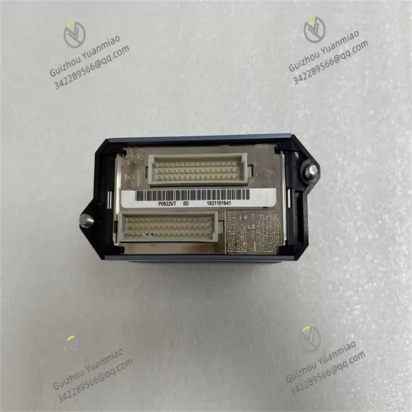
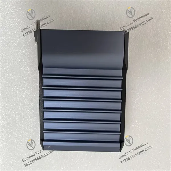
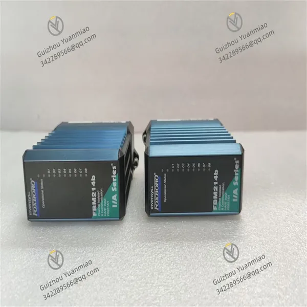
Foxboro FBM214 P0922VT HART Communication Input Interface Module
Foxboro FBM214 P0922VT HART Communication Input Interface Module photo-1
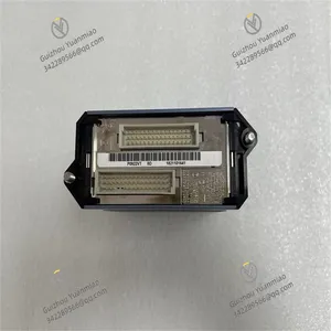
Foxboro FBM214 P0922VT HART Communication Input Interface Module photo-2
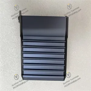
Foxboro FBM214 P0922VT HART Communication Input Interface Module photo-3
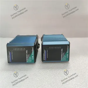
Foxboro FBM214 P0922VT HART Communication Input Interface Module photo-4
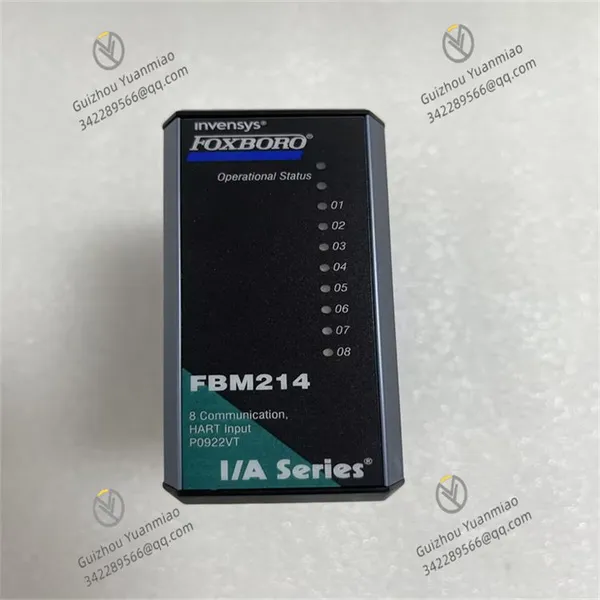
Negotiable MOQ: 1 Piece (Price negotiable depending on order volume and customization)
Key Specifications
Get Latest Price
Material:
Other, Global universal model
Condition:
Other, Global universal model
Task:
Other, Global universal model

Payment & Shipping
Payment Methods:
Port of Shipment:
China
Delivery Detail:
Delivery time depends on order quantity.
Material Other, Global universal model
Condition Other, Global universal model
Task Other, Global universal model
Mathematical Model Other, Global universal model
Signal Other, Global universal model
Customized Non-Customized
Structure Other, Global universal model
Dimensions 10.4cm×10.2cm×4.5cm
Weight 0.3kg
Input Range -2mA to 20mA
Foxboro FBM214 P0922VT
Basic Information
  • Model: FBM214 P0922VT.

  • Brand: Foxboro.

  • Number of Input Channels: 8 channels.

  • Dimensions: 10.4cm×10.2cm×4.5cm.

  • Weight: Approximately 0.3kg.

Functional Features
  • Input Types: Supports standard 4-20mA analog sensor signals and digital HART frequency shift keying (FSK) signals superimposed on 4-20mA analog input signals.

  • Communication Function: Each input channel is equipped with an FSK modem for two-way digital communication with HART field devices, supporting general commands required to connect HART field devices to the I/A Series® system database.

  • Isolation Characteristics: Current isolation is adopted between the 8 input channel groups, ground, and module logic, enhancing the system's anti-interference capability and safety.

  • High-Precision Measurement: High-precision measurement for each channel is achieved through sigma-delta data conversion technology, with an accuracy of up to ±0.15% of full scale and a resolution of 0.01% of full scale.

  • Compact and Durable Design: The compact and rugged structure is suitable for installation in cabinets in G3-level (harsh) environments.

  • Flexible Power Supply: A public isolated power supply is provided for all 8 channels, and external power supply is also optional. However, when two or more channels use a public external power supply, a cable balancing module is required to prevent channel crosstalk.

Technical Parameters
  • Input Range: -2mA to 20mA.

  • Response Time: 0.25 seconds.

  • Power Supply: 24VDC.

  • Power Consumption: 100mA.

  • Operating Temperature: -40°C to 80°C.

  • Humidity: 0% to 95% relative humidity, non-condensing.

FBM214 P0922VT (3)

The Foxboro FBM214 P0922VT is an input/output module in the field of industrial automation, commonly used in distributed control systems (DCS). The working principle is analyzed in detail from the aspects of signal processing flow, core functional modules, communication mechanisms, etc. as follows:
I. Overall Architecture and Functional Positioning
The FBM214 P0922VT belongs to the fieldbus components (FBM) of the Foxboro DeltaV system, mainly used for the collection and control of analog inputs (such as voltage and current signals) and digital inputs/outputs (switching signals). Its core function is to convert signals from field sensors or actuators into digital signals for communication with the DeltaV controller, while supporting signal conditioning, isolation, and diagnosis to ensure reliable transmission of industrial process data.
II. Working Principle of Signal Processing
  1. Analog Input Processing (AI)
  • Signal Access and Conditioning
    It supports receiving 4-20mA current signals or 0-10V voltage signals (the specific input type is configurable). After the signals enter the module through the differential input channels, they first pass through the signal conditioning circuit, including filtering (to eliminate high-frequency noise), amplification (to match the analog-to-digital conversion range), and linearization processing (to correct signal nonlinear errors).
    For example, after the 4-20mA signal is converted into a voltage signal by a resistor, the gain is adjusted by an operational amplifier to ensure that the signal range input to the ADC matches the module's measurement range.

  • Analog-to-Digital Conversion (ADC)
    The conditioned analog signals are converted into digital signals by a high-precision analog-to-digital converter (ADC). The FBM214 typically uses a Σ-Δ type ADC with a resolution of 16 bits or higher, and the conversion accuracy can reach ±0.05% of full scale, ensuring minimal signal quantization error.

  • Calibration and Compensation
    The module has a built-in self-calibration mechanism, which regularly calibrates the zero point and gain of the ADC through a hardware reference source (such as a precision voltage source), and also supports temperature compensation (for the impact of ambient temperature changes on signals) to ensure the stability of measurement accuracy.

  • Digital Input/Output Processing (DI/DO)
    • Digital Input (DI)
      Field switch signals (such as relay contacts and proximity switches) are connected to the module through input channels, isolated by optocouplers, converted into TTL level signals, and read by the microprocessor. The isolation design can prevent field electrical interference from affecting the module's operation and protect the internal circuit from high-voltage impact.
      Typical parameters: input voltage range 24VDC ±10%, response time ≤10ms.

    • Digital Output (DO)
      After the module receives the digital control signal from the controller, it outputs through a solid-state relay (SSR) or relay to drive field actuators (such as solenoid valves and indicator lights). The output channels also have electrical isolation (isolation voltage is usually ≥2500Vrms) to avoid the impact of output loop faults on the module.
      Output types: usually dry contact output (relay type) or 24VDC level output (solid-state type), and the maximum load current can reach 1A/channel.

  • Signal Isolation and Anti-Interference Design
    • Electrical Isolation Mechanism
      The FBM214 adopts a single-channel isolation design (analog and digital channels are independently isolated), and realizes electrical isolation between channels and from the system power supply through transformer coupling (analog) or optoelectronic coupling (digital), preventing common-mode interference and ground loop effects to ensure stability in complex electromagnetic environments.
      Isolation index: isolation voltage between channels ≥2500Vrms, isolation voltage between power supply and signal ground ≥1500Vrms.

    • Anti-Interference Measures
      In addition to isolation, the module also integrates an EMI (electromagnetic interference) filter circuit inside, and the external cable is required to use shielded twisted-pair wires to reduce the interference of external electromagnetic radiation on the signal. At the same time, it meets the environmental requirements of anti-vibration and anti-shock in industrial fields (such as vibration tolerance of 5g rms, 20-500Hz).

    FBM214 P0922VT (1)

    III. Principle of Communication and Data Interaction
    1. Communication with the DeltaV System
    • Fieldbus Connection
      The FBM214 is connected to the DeltaV controller (CP) through FOUNDATION Fieldbus or a dedicated communication bus. The communication protocol follows IEEE 1118, the transmission rate is 268.75kbps, and the maximum communication distance can reach 1800 meters (using shielded twisted-pair wires).
      Communication mode: master-slave half-duplex communication, and the controller polls the FBM module periodically to obtain input data or issue output commands.

  • Data Processing and Protocol Conversion
    • Microprocessor Control
      The module has a built-in microprocessor (such as ARM or a dedicated MCU), which is responsible for coordinating ADC/DAC conversion, signal processing, communication protocol analysis, and fault diagnosis. After the input data is processed (such as engineering quantity conversion and unit conversion), it is packaged and sent to the controller according to the protocol. After receiving the controller's instructions, it parses and executes output control or parameter configuration (such as range setting and filter coefficient adjustment).

    • Real-time Performance and Reliability
      The communication protocol has an error checking mechanism (such as CRC checking) to ensure the accuracy of data transmission. It also supports hot-swapping, and the online replacement of the module does not affect the operation of other parts of the system, improving the maintainability of the industrial system.

    IV. Diagnostic and Fault Handling Mechanisms
    • Built-in Diagnostic Function
      The FBM214 monitors its own working status in real time, including:

      • Channel diagnosis: detecting whether the input signal is over-limit, open circuit, or short circuit (such as triggering an alarm when the analog input exceeds the range);

      • Hardware diagnosis: monitoring the power supply voltage, temperature, and working status of ADC/DAC, and reporting to the controller through the module indicator light (such as LED light) or communication interface when abnormalities are found;

      • Communication diagnosis: detecting whether the bus connection is interrupted and whether the data transmission is wrong, and automatically retransmitting the lost data packets.

    • Fault Response and Protection
      When a fault occurs, the module can perform protection actions according to the preset logic (such as keeping the digital output in the last state or forcing it to a safe value), and generate alarm information through the DeltaV system to facilitate maintenance personnel to locate the problem.

    FBM214 P0922VT (2)

    V. Application Scenarios and Workflow Examples
    Take a temperature monitoring system as an example:
    1. Field Signal Access: The 4-20mA signal output by the temperature transmitter is connected to the analog input channel of the FBM214;

    2. Signal Processing: The current signal is conditioned and converted into a digital value by the ADC, and the microprocessor performs linearization calculations according to the range of the temperature transmitter (such as 0-100℃) to convert it into an actual temperature value;

    3. Data Transmission: The temperature data is sent to the DeltaV controller through Fieldbus, and the controller judges whether to trigger an alarm or control action according to the process requirements;

    4. Output Control (if needed): The controller issues instructions to the digital output channel of the FBM214 to drive the relay to control the start and stop of the heating equipment, realizing closed-loop control.

    VI. Summary of Core Technical Parameters
    Parameter Category Typical Indicators
    Input Types Analog: 4-20mA, 0-10V; Digital: 24VDC switching signals
    Number of Channels Usually 16 analog inputs + 8 digital inputs/outputs (subject to the model)
    Accuracy Analog: ±0.05% of full scale; Digital: response time ≤10ms
    Isolation Voltage Isolation between channels and power supply ≥2500Vrms
    Communication Protocol FOUNDATION Fieldbus, 268.75kbps, maximum distance 1800 meters
    Operating Temperature -40℃ to 70℃, storage temperature -55℃ to 85℃
    Diagnostic Function Real-time monitoring of channel faults, hardware faults, and communication faults, supporting LED indication and bus alarm
    Product Tags: FBM214 , FBM214B , P0927AH

    Send Inquiry to This Supplier

    * Message
    0/5000

    Want the best price? Post an RFQ now!
    Verified Business License
    Business Type
    Trading Company
    Year Established
    2014
    Factory Size
    1,000-3,000 square meters
    Product Certifications
    SA8000