

Home > Electrical & Electronics > Electrical Control System > Foxboro FBM219 P0916RH Discrete Input/Output Interface Module
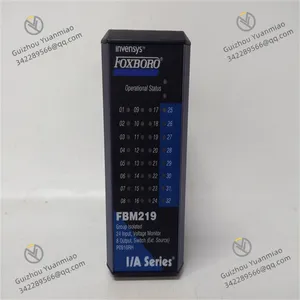
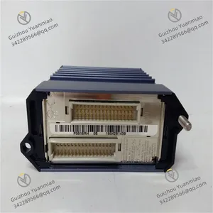
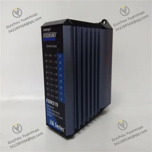
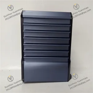
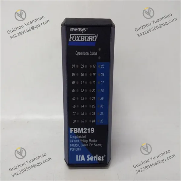
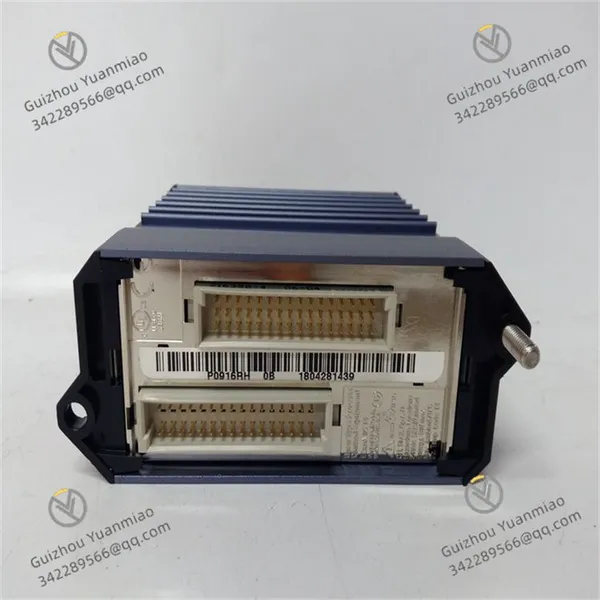
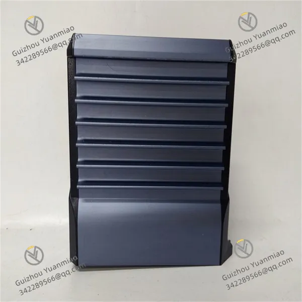
Foxboro FBM219 P0916RH Discrete Input/Output Interface Module

Negotiable
MOQ: 1 Piece (Price negotiable depending on order volume and customization)
Key Specifications
Get Latest Price
Material:
Other, Global universal model
Condition:
Other, Global universal model
Task:
Other, Global universal model
Payment & Shipping
Payment Methods:
Port of Shipment:
China
Delivery Detail:
Delivery time depends on order quantity.
Related Products
-
 Foxboro FBM222 P0926TL Fieldbus ModuleNegotiableMOQ: 1 Piece
 -
Foxboro FBM223 P0917HD Digital I/O ModuleNegotiableMOQ: 1 Piece
-
Foxboro FBM224 P0926GG Modbus Communication ModuleNegotiableMOQ: 1 Piece
-
Foxboro FBMSSW Field Bus ModuleNegotiableMOQ: 1 Piece
-
Foxboro FBMSVH Field Bus ModuleNegotiableMOQ: 1 Piece
Material
Other, Global universal model
Condition
Other, Global universal model
Task
Other, Global universal model
Mathematical Model
Other, Global universal model
Signal
Other, Global universal model
Customized
Non-Customized
Structure
Other, Global universal model
Operating Temperature
-20 to +60°C
Vibration
7.5m/s² (5 to 500Hz)
Relative Humidity
5 to 95% (non-condens)
Functional FeaturesTechnical ParametersApplication Scenarios

Send Inquiry to This Supplier


Business Type
Trading Company
Year Established
2014
Factory Size
1,000-3,000 square meters
Product Certifications
SA8000
You May Also Like
-
Foxboro FBMSVL Fieldbus ModuleNegotiableMOQ: 1 Piece
-
Foxboro FCM2F2 P0914YZ Optical Fiber Communication ExtenderNegotiableMOQ: 1 Piece
-
Foxboro FEM100 P0973CA Fieldbus Expansion ModuleNegotiableMOQ: 1 Piece
-
Foxboro FBM241 P0914TG 8-Channel Voltage Monitoring ModuleNegotiableMOQ: 1 Piece
-
Foxboro FBM242 P0916TA Discrete Output Interface ModuleNegotiableMOQ: 1 Piece
-
Foxboro FBM230 P0926GU Switch Quantity I/O ModuleNegotiableMOQ: 1 Piece
-
Foxboro FBM232 P0926GW Ethernet Communication ModuleNegotiableMOQ: 1 Piece
-
Foxboro FBM233 P0926GX Analog Input ModuleNegotiableMOQ: 1 Piece
-
Foxboro FBM237 RH914XS Output ModuleNegotiableMOQ: 1 Piece
-
Foxboro FBM240 P0917GZ Fieldbus ModuleNegotiableMOQ: 1 Piece


