

Home > Electrical & Electronics > Electrical Control System > Foxboro FBM203 P0914SV 8-Channel Isolated RTD Input Module
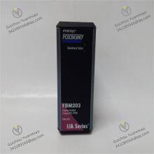
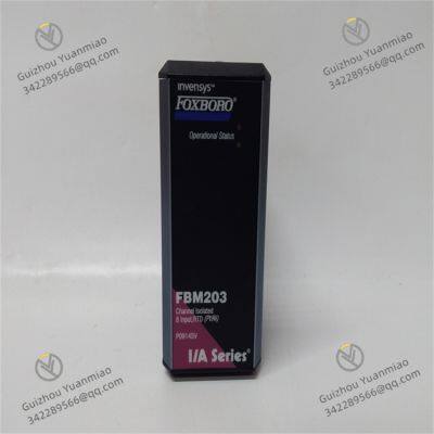
Foxboro FBM203 P0914SV 8-Channel Isolated RTD Input Module

Negotiable
MOQ: 1 Piece (Price negotiable depending on order volume and customization)
Key Specifications
Get Latest Price
Material:
Other, Global universal model
Condition:
Other, Global universal model
Task:
Other, Global universal model
Payment & Shipping
Payment Methods:
Port of Shipment:
China
Delivery Detail:
Delivery time depends on order quantity.
Related Products
-
 Foxboro FBM204 P0914SY I/O ModuleNegotiableMOQ: 1 Piece
 -
Foxboro FBM205 P0914XG 8-Channe I/O Interface ModuleNegotiableMOQ: 1 Piece
-
Foxboro FBM206 P0916CQ Pulse Input ModuleNegotiableMOQ: 1 Piece
-
Foxboro FBM207 P0914TD Discrete Input Interface ModuleNegotiableMOQ: 1 Piece
-
Foxboro FBM208 P0914TB Discrete Output Interface ModuleNegotiableMOQ: 1 Piece
Material
Other, Global universal model
Condition
Other, Global universal model
Task
Other, Global universal model
Mathematical Model
Other, Global universal model
Signal
Other, Global universal model
Customized
Non-Customized
Structure
Other, Global universal model
Weight
0.4kg
Dimensions
4.5cm×11cm×11.5cm
Power Supply
24VDC
Foxboro FBM203 P0914SVBasic InformationFunctional CharacteristicsWorking PrincipleApplication FieldsIntegration with Control Systems

Send Inquiry to This Supplier

* Email
Want the best price?
Post an RFQ now!

1Yr
Business Type
Trading Company
Year Established
2014
Factory Size
1,000-3,000 square meters
Product Certifications
SA8000
You May Also Like
-
Foxboro FBM211 P0914TN Discrete Input ModuleNegotiableMOQ: 1 Piece
-
Foxboro FBM212 P0914XL Interface ModuleNegotiableMOQ: 1 Piece
-
Foxboro FBM214 P0922VT HART Communication Input Interface ModuleNegotiableMOQ: 1 Piece
-
Foxboro FBM215 P0917TQ HART Communication Output ModuleNegotiableMOQ: 1 Piece
-
Foxboro FBM216 P0917TN I/O ModuleNegotiableMOQ: 1 Piece
-
Foxboro FBM217 P0914TR Fieldbus ModuleNegotiableMOQ: 1 Piece
-
Foxboro FBM218 HART Communication Redundant Output Interface ModuleNegotiableMOQ: 1 Piece
-
Foxboro FBM219 P0916RH Discrete Input/Output Interface ModuleNegotiableMOQ: 1 Piece
-
Foxboro FBM222 P0926TL Fieldbus ModuleNegotiableMOQ: 1 Piece
-
Foxboro FBM223 P0917HD Digital I/O ModuleNegotiableMOQ: 1 Piece


