



Home > Electrical & Electronics > Electrical Control System > Foxboro FBM218 HART Communication Redundant Output Interface Module

Foxboro FBM218 HART Communication Redundant Output Interface Module
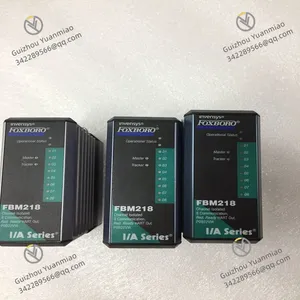
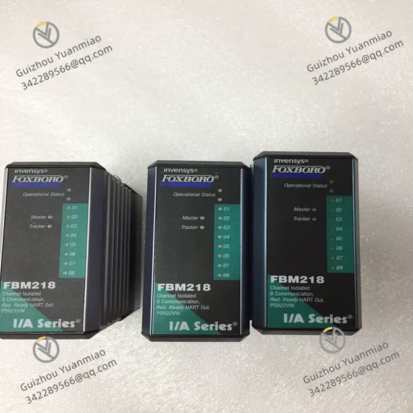
Foxboro FBM218 HART Communication Redundant Output Interface Module photo-1
Negotiable MOQ: 1 Piece (Price negotiable depending on order volume and customization)
Key Specifications
Get Latest Price
Material:
Other, Global universal model
Condition:
Other, Global universal model
Task:
Other, Global universal model

Payment & Shipping
Payment Methods:
Port of Shipment:
China
Delivery Detail:
Delivery time depends on order quantity.
Material Other, Global universal model
Condition Other, Global universal model
Task Other, Global universal model
Mathematical Model Other, Global universal model
Signal Other, Global universal model
Customized Non-Customized
Structure Other, Global universal model
Operating Temperature -40°C to +85°C
Power Supply 10 to 30V DC
Isolation Voltage 1500V DC
Maximum Current 5A per channel
Foxboro FBM218
Functional Features
  • Output Channels: 8 isolated output channels, each providing standard 4-20mA analog output signals or digital HART frequency shift keying (FSK) signals superimposed on 4-20mA analog outputs.

  • Communication Capability: Each output channel is equipped with a dedicated FSK modem for two-way digital communication with HART field devices, supporting HART universal commands required for interfacing field devices with Foxboro DCS.

  • Current Isolation: All output channels are current-isolated from each other, ground, and module logic, effectively protecting the module from electrical interference and ground loops.

  • Redundancy Design: The module pair provides FBM-level redundancy. When combined as a pair, one acts as the Master and the other as the Tracker. If one module detects a fault, its output is driven to 0mA, and the corresponding channel in the normal module automatically continues to supply appropriate current to the output current loop.

  • Safety Configuration: The module offers rich configurable options for output safety, including fail-safe actions (hold/retreat), analog output fail-safe retreat data (multichannel-based), fieldbus fail-safe enablement, and fieldbus fault protection delay time.

  • Status Indication: Light-emitting diodes (LEDs) on the front of the module provide visual indication of the module's operating status and channel communication activities, enabling users to intuitively understand the module's working conditions.

Technical Parameters
  • Operating Temperature: -40°C to +85°C.

  • Power Supply: 10 to 30V DC.

  • Maximum Current: 5A per channel.

  • Isolation Voltage: 1500V DC.

Application Scenarios
  • Oil and Gas: Used in oil extraction, refining, and natural gas processing to control various field devices such as valves and pumps, enabling precise control and monitoring of process parameters.

  • Chemical Processing: Controls and monitors equipment like reaction kettles and conveying pipelines in chemical production to ensure safe and stable production processes.

  • Power Generation: Suitable for various control systems in power plants, such as control of boilers, turbines, and monitoring and management of power distribution systems.

  • Other Industrial Sectors: Industries such as food and beverage, water and wastewater treatment, pulp and paper, etc., can use the FBM218 module for process control and monitoring involving HART communication.

FBM218

Common Faults and Solutions for Foxboro FBM218 ModuleI. Overview
The FBM218 is a 16-channel analog input module (typically model P0926TR) in Emerson's DeltaV control system, mainly used to collect analog signals (such as 4-20mA current, 0-10V voltage, etc.) from field devices and convert them into digital signals for transmission to the controller. The module supports the HART communication protocol, interacts with intelligent instruments, and features high precision, anti-interference, and self-diagnosis functions, widely applied in industrial process control scenarios such as chemical, petroleum, and power industries.
II. Common Fault Types and Solutions(1) Power Failures
  1. Module Power Indicator (PWR) Off
  • Possible Causes:

    • External 24VDC power supply not connected or voltage abnormal (below 21.6V or above 26.4V).

    • Loose power terminal connections, poor contact, or cable open circuit.

    • Damaged module power interface or internal power circuit failure.

  • Solutions:

    • Use a multimeter to check the power input voltage, ensuring it is within the range of 24VDC±5%.

    • Inspect power terminal block wiring, re-tighten, or replace cables (shielded twisted pair is recommended).

    • If the power supply is normal but the indicator remains off, attempt to replace the module power interface or contact the manufacturer for maintenance

  • Power Indicator Flashing
    • Possible Causes:

      • Voltage fluctuations in the power input (e.g., interference due to poor grounding).

      • Internal power overload or poor heat dissipation in the module (operating temperature exceeds -20°C~+70°C).

    • Solutions:

      • Check if the power grounding meets requirements (independent grounding, grounding resistance

      • Clean dust from the module's cooling holes, ensure good ventilation in the installation environment, and avoid high-temperature conditions

    (2) Communication Failures
    1. Bus Communication Failure (COM Light Off or Flashing)
    • Possible Causes:

      • Incorrect wiring or disconnection of DeltaV fieldbus (e.g., ControlNet/EtherNet/IP).

      • Bus terminal resistors not installed or damaged (ControlNet requires 120Ω resistors at both ends).

      • Module address conflict or communication protocol mismatch with the controller.

    • Solutions:

      • Use a multimeter to check the continuity of bus cables and confirm correct polarity (ControlNet requires distinguishing between A/B wires).

      • Inspect the installation status of terminal resistors and replace damaged ones.

      • Verify the uniqueness of the module address in DeltaV configuration software, redownload the configuration, and restart the module

  • HART Communication Abnormality (Channels with HART Function Only)
    • Possible Causes:

      • HART signal cables not connected as required (250Ω load resistor needs to be connected in parallel).

      • HART address conflict in intelligent instruments or incorrect setting of communication parameters (e.g., baud rate, parity).

      • Faulty module HART communication chip or electromagnetic interference.

    • Solutions:

      • Check HART loop wiring to ensure correct resistor connection and cable length does not exceed 1500 meters.

      • Reconfigure the instrument's HART parameters through the DeltaV system or handheld operator (e.g., Rosemount 475).

      • Add a shielding layer to HART cables and ground them reliably; replace the module if necessary

    (3) Signal Acquisition Failures
    1. No Signal Input in Channel (Display Value is 0 or Fixed Deviation)
    • Possible Causes:

      • Abnormal power supply to field instruments (e.g., 24VDC power interruption).

      • Signal cable open circuit, short circuit, or poor contact (e.g., loose terminal block screws).

      • Damaged module channel hardware (e.g., ADC converter failure).

    • Solutions:

      • Check the instrument's power supply and use a multimeter to measure the voltage at the signal terminal (4-20mA loop should be ≥10VDC).

      • Inject standard signals (e.g., 4mA, 12mA, 20mA) into the channel input with a signal generator and observe if the module display is normal.

      • If there is still no response after injecting the signal, try changing the channel configuration in DeltaV configuration; replace the module if ineffective

  • Excessive Deviation or Fluctuation in Signal Measurement Values
    • Possible Causes:

      • Signal cables subject to electromagnetic interference (e.g., laid close to power cables).

      • Zero drift in field instruments or mismatch between range settings and the module.

      • Gain drift in module channels or improper setting of filtering parameters.

    • Solutions:

      • Re-lay signal cables, maintain at least 30cm distance from power cables, and use twisted shielded wires with single-end grounding.

      • Calibrate the instrument's zero and range (via HART communication or field buttons) to ensure consistency with module configuration.

      • Adjust the module's filtering time constant in the DeltaV system (e.g., increase from 0.1s to 1s) to reduce noise interference

    Product Tags: FBM218

    Send Inquiry to This Supplier

    * Message
    0/5000

    Want the best price? Post an RFQ now!
    Verified Business License
    Business Type
    Trading Company
    Year Established
    2014
    Factory Size
    1,000-3,000 square meters
    Product Certifications
    SA8000

