

Home > Electrical & Electronics > Electrical Control System > Foxboro P0916AE Compression Terminal Base
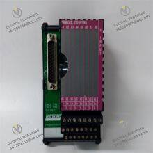
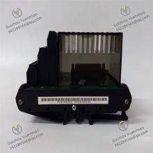
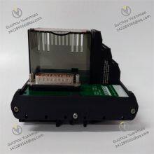
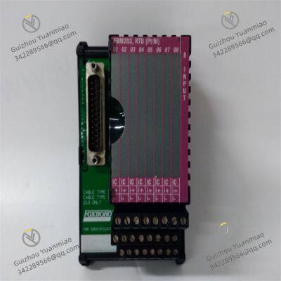
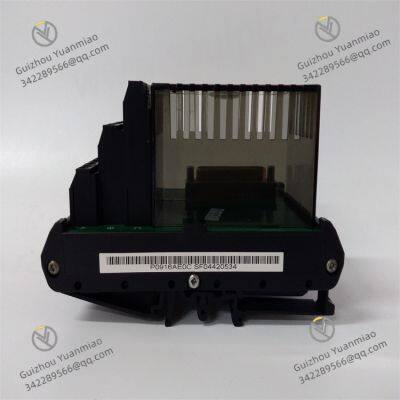
Foxboro P0916AE Compression Terminal Base

Negotiable
MOQ: 1 Piece (Price negotiable depending on order volume and customization)
Key Specifications
Get Latest Price
Material:
Other, Global universal model
Condition:
Other, Global universal model
Task:
Other, Global universal model
Payment & Shipping
Payment Methods:
Port of Shipment:
China
Delivery Detail:
Delivery time depends on order quantity.
Related Products
-
 FOXBORO P0916AJ | I/O Interface ModuleNegotiableMOQ: 1 Piece
 -
Foxboro P0916BX Termination AssemblyNegotiableMOQ: 1 Piece
-
Foxboro P0916CC I/A Series ModuleNegotiableMOQ: 1 Piece
-
Foxboro FBM242 P0916NG Switch Terminal BlockNegotiableMOQ: 1 Piece
-
FOXBORO P0916PH P0916JS Terminal Block ModuleNegotiableMOQ: 1 Piece
Material
Other, Global universal model
Condition
Other, Global universal model
Task
Other, Global universal model
Mathematical Model
Other, Global universal model
Signal
Other, Global universal model
Customized
Non-Customized
Structure
Other, Global universal model
Basic InformationFunctional FeaturesWorking Principle

Send Inquiry to This Supplier

* Email
Want the best price?
Post an RFQ now!

1Yr
Business Type
Trading Company
Year Established
2014
Factory Size
1,000-3,000 square meters
Product Certifications
SA8000
You May Also Like
-
FOXBORO P0916XT Contact Sense Input ModuleNegotiableMOQ: 1 Piece
-
Foxboro P0917MF Control ProcessorNegotiableMOQ: 1 Piece
-
Foxboro P0917XV Compression Termination AssemblyNegotiableMOQ: 1 Piece
-
Foxboro P0924JH Compact Power SupplyNegotiableMOQ: 1 Piece
-
Foxboro P0926GH Communication TerminalNegotiableMOQ: 1 Piece
-
FOXBORO RH916XG Input ModuleNegotiableMOQ: 1 Piece
-
Foxboro FBM217 RH916XZ Discrete Input Interface ModuleNegotiableMOQ: 1 Piece
-
Foxboro FBM242 RH916YY Discrete Output Interface ModuleNegotiableMOQ: 1 Piece
-
Foxboro FBM207B P0916JS Contact Sense ModuleNegotiableMOQ: 1 Piece
-
Foxboro FBM211 P0916JT Fieldbus ModuleNegotiableMOQ: 1 Piece


