Material
Other, Global universal model
Condition
Other, Global universal model
Task
Other, Global universal model
Mathematical Model
Other, Global universal model
Signal
Other, Global universal model
Customized
Non-Customized
Structure
Other, Global universal model
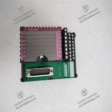
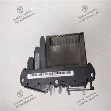
Foxboro P0916CC
Functional Purposes
It is a 4-20mA output termination assembly, providing safe and reliable connections for 4-20mA output signals of Foxboro I/A series controllers. It is used to connect field devices (such as transmitters and actuators) with control systems, enabling signal acquisition, conversion, and transmission. When combined with the universal FBM 247, it can process multiple signal types, including analog, digital, HART inputs, and outputs. Each channel can be configured point-by-point through software, eliminating a significant portion of grouping work.
Product Features
High Reliability: Designed for industrial environments and manufactured with high-quality materials, it can adapt to harsh industrial sites, featuring high reliability and stability.
Redundant Configuration: Enables asset availability, enhances system reliability and stability, and reduces the risk of system downtime caused by single-point failures.
Software Configurable: It can be configured through software without additional hardware, offering convenience and flexibility for customized settings based on actual application requirements.
Technical Parameters
The power supply voltage is typically 200V, and the power is 1800. As a 4-20mA output termination assembly, it ensures high precision and stability in signal transmission, guaranteeing the accuracy and reliability of output signals.
Application Fields
Widely applied in various industrial automation fields, such as control systems in chemical, petroleum, power, metallurgy, pharmaceutical, and other industries, to achieve precise control and monitoring of field devices.


Working Principle of Foxboro P0916CCFunctional Positioning and System Architecture
Foxboro P0916CC is a signal interface module in the field of industrial automation, typically used in process control systems to implement analog signal input/output processing. Its working principle is based on signal conditioning, electrical isolation, analog-to-digital/digital-to-analog conversion, and communication protocol integration, with the core goal of ensuring reliable transmission and processing of industrial field signals (such as current and voltage) between control systems.
Working Principle
1. Analog Signal Input Processing (Input Channel)
Signal Acquisition and Conditioning:
It supports inputs of standard industrial current signals such as 0-20mA/4-20mA. After being connected via terminals, the current signals are first converted into voltage signals by a signal conditioning circuit (such as a precision resistor network), and then filtered (to eliminate high-frequency interference) and amplified (to match the subsequent circuit level).
Analog-to-Digital Conversion (A/D Conversion):
Using sigma-delta modulation technology (similar to P0916AJ), high-precision conversion (usually 16-bit or higher resolution) is achieved through oversampling and noise shaping. The converted digital signals are further processed by a digital filter to reduce quantization errors and random noise.
Electrical Isolation:
Each input channel uses transformer isolation or optocoupler isolation technology to electrically isolate field signals from the control system (isolation voltage typically ≥500V), preventing interferences such as ground loops and surges from affecting system stability while protecting the internal circuit of the module.
2. Analog Signal Output Processing (Output Channel)
Digital-to-Analog Conversion (D/A Conversion):
Receiving digital control signals (such as PLC or DCS commands) from the control system, it converts them into analog voltage signals through a DAC chip, and then converts them into 0-20mA/4-20mA current signals via a current drive circuit to drive actuators (such as valves and motors).
Signal Amplification and Driving:
The output circuit includes a power amplification module to ensure that the current signal remains stable during long-distance transmission (such as between field devices and control cabinets) and avoids signal attenuation.
Fault Protection:
It has built-in overcurrent protection and short-circuit protection mechanisms. When the output load is abnormal, the signal is automatically cut off to prevent module damage.
3. Communication and Protocol Processing
Bus Communication Interface:
It communicates with the control system host through field bus protocols (such as Foxboro's I/A Series bus and Modbus), receiving configuration commands (such as channel parameters and range) and uploading real-time data.
Data Transmission Mechanism:
It adopts periodic scanning or event-triggered modes:
Periodic Scanning: Collects input signals at a fixed frequency and sends them to the host.
Event Triggered: Actively uploads data when the signal change exceeds a set threshold (such as rate-of-change limitation) to reduce bus load.
4. Power Supply and Logic Control
Power Management:
It usually uses 24VDC power supply. Internally, a DC-DC converter generates multiple isolated power supplies (such as for analog circuits, digital circuits, and isolation devices) to ensure independent operation of each module and reduce power supply interference.
Logic Control Unit:
It is equipped with a built-in microprocessor or FPGA, responsible for coordinating the work of each functional module, executing configuration commands (such as channel calibration and range setting), and feeding back the operating status (such as power supply, communication, and fault) through status indicator lights (LED).
Key Technical Characteristics and Working Mechanisms
1.Principle of High-Precision Signal Conversion
Details of Sigma-Delta Technology:
Through high-frequency sampling (such as above 1MHz) and noise shaping, quantization noise is pushed to the high-frequency band and then filtered out by a low-pass filter to achieve high-precision conversion (error ≤0.05% FS). For example, when a 20mA signal is input, the Deviation between the converted digital value and the theoretical value is less than 0.01mA.
2. Implementation Modes of Electrical Isolation
Transformer Isolation: Suitable for AC signal isolation, transmitting signals through electromagnetic coupling with a wide isolation bandwidth.
Optocoupler Isolation: Using optical signal transmission, it has a fast response speed, is often used for DC signal isolation, and the isolation voltage can reach more than 1000V.
3. Principles of Anti-Interference Design
Workflow Examples
Signal Input Workflow:
4-20mA current signal output by field sensors (such as pressure transmitters) → connected to P0916CC input terminals → converted into voltage by the signal conditioning circuit → converted into digital values by sigma-delta ADC → transmitted to the logic control unit through the isolation circuit → sent to the DCS system via the bus.
Signal Output Workflow:
DCS sends control commands (digital values) → transmitted to P0916CC via the bus → the logic control unit parses the commands → DAC converts them into voltage signals → the current drive circuit generates 4-20mA signals → output to actuators (such as control valves) after isolation.


