

GE IC698PSA100 Power Module
Related Products
-
 GE 369-HI-0-M-0-0-0 Motor Protection RelayNegotiableMOQ: 1 Piece
 -
GE 369-HI-R-0-0-E-0-E Motor Management RelayNegotiableMOQ: 1 Piece
-
GE 151X1235BC01SA01 10-slot Ethernet SwitchNegotiableMOQ: 1 Piece
-
GE 369-LO-0-M-F-E-0-0 Digital RelayNegotiableMOQ: 1 Piece
-
GE SR469 Series Motor Management RelayNegotiableMOQ: 1 Piece
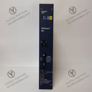
GE IC698PSA100 power module
IC698PSA100, as the power module of the GE PACSystem RX7i series, its core function is to convert the external input
alternating current (or direct current) into the stable direct current power supply required by the industrial control
system. Meanwhile, it has multiple protection mechanisms to ensure the reliable operation of the system. The
following is a detailed analysis of its working principle from aspects such as energy conversion, voltage regulation, and
protection mechanism:
I. Input power processing and Energy Conversion
Input power supply adaptation
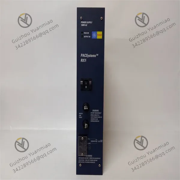
The IC698PSA100 supports a wide range of input: 85-264VAC (AC) or 100-150VDC (DC). It converts AC to DC through
an internal rectifier circuit (if the input is DC, it directly enters the subsequent processing).
The input terminals adopt a spiral design and support AWS #16 copper wire connection to ensure the stability and
anti-interference ability of the input power supply.
Core architecture of power conversion
The Switching Power Supply technology is adopted. Through the on-off control of high-frequency switching tubes
(such as MOSFET or IGBT), the input high-voltage direct current is converted into high-frequency pulse voltage, and
then rectified and filtered after being stepped down by the transformer. Generate the required low-voltage DC output
(+5VDC, +12VDC, -12VDC).
Compared with traditional linear power supplies, switching power supplies have the advantages of high efficiency
(power factor ≥0.99), small size and low heat generation, making them suitable for long-term operation in industrial
control scenarios.
Ii. Output Voltage Regulation and Stabilization Mechanism
Multi-channel independent voltage stabilization
The module provides three outputs:
+5VDC (nominal value) : Up to 20A, it is used to supply power to core components such as cpus and communication
modules. The voltage accuracy is controlled within 4.875-5.25V, meeting the high stability requirements of digital
circuits.
+12VDC (nominal value) : Maximum 2A, providing power for peripheral devices such as I/O modules;
-12VDC (nominal value) : Up to 1A, used to support circuits that require negative voltage (such as operational
amplifiers).
Each output channel is monitored for voltage fluctuations in real time through a feedback circuit (such as a voltage
divider resistor + error amplifier), and the conduction time of the switch tube is adjusted through PWM (Pulse Width
Modulation) technology to achieve closed-loop voltage stabilization control, ensuring that the output voltage remains
stable when the load changes.
Dynamic response and retention characteristics
The module features "traversal time" (minimum 15ms) and "hold time" (minimum 5ms) : When the input power is
briefly interrupted, the internal energy storage components (such as large-capacity capacitors) can maintain a stable
output voltage, preventing the control system from restarting or malfunctions due to grid fluctuations. It is suitable for
industrial environments with high requirements for power continuity.
Iii. Protection Mechanism and Fault Diagnosis
Overvoltage Protection (OVP
When the output voltage of + 5VDC exceeds the threshold of 5.7-6.7V, the overvoltage protection circuit will
immediately act by turning off the switch tube or triggering the current-limiting circuit to prevent high voltage from
damaging the back-end equipment.
Overcurrent Protection (OCP
Independent overcurrent thresholds are set for each output channel: 21A for +5VDC, 2.5A for +12VDC, and 3.5A
for -12VDC. When the load current exceeds the threshold, the protection circuit reduces the PWM duty cycle or
temporarily cuts off the output to prevent the power module from overheating and getting damaged due to overload.
After the fault is eliminated, it can automatically recover or reset by restarting the module.
Overheat Protection (OTP)
The module integrates a temperature sensor internally to monitor the temperature of power devices in real time.
When the temperature exceeds the set threshold (such as 85°C), the overheat protection mechanism is activated,
gradually reducing the output power or cutting off the output. The "over-temperature indicator light" on the front side
lights up. Once the temperature drops, it automatically resumes operation to prevent device aging or burnout due to
poor heat dissipation.
Output enable control
The front switch can be manually "enabled" or "disabled" for the output channel. When disabled, only the DC output is
cut off without affecting the AC input, which is convenient for maintenance or troubleshooting, and at the same time
avoids the impact of hot plugging on the module.
Iv. Industrial Environment Adaptability Design
Isolation and Anti-interference
The input and output are designed with electrical isolation (isolation withstand voltage 1500VDC) to prevent external
grid interference from coupling to the control system through the power supply, and at the same time avoid current
backflow to the input side in case of module failure.
The internal filter circuit can suppress high-frequency noise and meet the EMC (Electromagnetic Compatibility)
requirements of industrial sites.
Environmental tolerance
The operating temperature range is 0°C to 60°C, supporting operation in hazardous environments of level 1 and Zone
2, and adapting to complex working conditions such as high temperatures and dust in industrial sites. The front
indicator light (normal on site, normal output, over-temperature) provides real-time feedback on the operating status,
facilitating on-site maintenance.
V. Collaborative Operation with the RX7i System
The module is installed in slot 0 of the RX7i rack and supplies power to other modules (such as CPU and I/O modules)
through the backplane. When the power supply is abnormal (such as overvoltage, overcurrent, or overheating), in
addition to the local indicator light alarm, the fault signal can also be transmitted to the CPU through backplane
communication to achieve system-level fault diagnosis and alarm, ensuring the safe operation of the control system.
Summary
The IC698PSA100 power module achieves efficient energy conversion through switching power supply technology.
Combined with multi-channel voltage regulation, multiple protection mechanisms and industrial-grade environment
design, it provides stable and reliable power support for the RX7i system. Its working principle runs through the entire
process of "input adaptation - power conversion - voltage regulation control - fault protection". It is a typical
representative of the power supply subsystem in industrial automation control systems.

Send Inquiry to This Supplier


You May Also Like
-
GE F650BABF2G0LOSHE Multi-functional Digital ControllerNegotiableMOQ: 1 Piece
-
GE F650-G-N-A-B-F-2-G-1-HI-C-E Comprehensive Protection DeviceNegotiableMOQ: 1 Piece
-
GE IC697PCM711 Single-slot Programmable Coprocessor ModuleNegotiableMOQ: 1 Piece
-
GE IC697MDL750 Discrete Output ModuleNegotiableMOQ: 1 Piece
-
GE VME-5565 Reflective Memory VME Node CardNegotiableMOQ: 1 Piece
-
GE VME-7807RC High-performance Single-board ComputerNegotiableMOQ: 1 Piece
-
GE VMIVME-2510B 64-bit TTL Digital Input/output BoardNegotiableMOQ: 1 Piece
-
GE VMIVME-2540-000 Intelligent ControllerNegotiableMOQ: 1 Piece
-
GE VMIVME-4116 Data Acquisition Control Board Card NegotiableMOQ: 1 Piece
-
GE VMIVME-4140 32-channel 12-bit Analog Output Circuit BoardNegotiableMOQ: 1 Piece


