

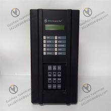
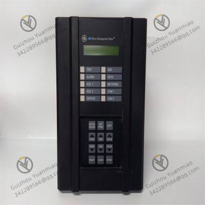
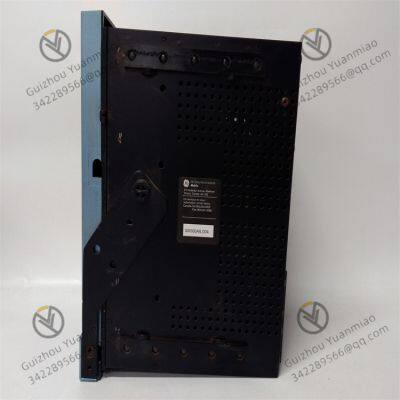
GE 369-LO-0-M-F-E-0-0 Digital Relay

Related Products
-
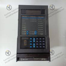
 GE SR469 Series Motor Management RelayNegotiableMOQ: 1 Piece
 -
GE F650BABF2G0LOSHE Multi-functional Digital ControllerNegotiableMOQ: 1 Piece
-
GE F650-G-N-A-B-F-2-G-1-HI-C-E Comprehensive Protection DeviceNegotiableMOQ: 1 Piece
-
GE IC697PCM711 Single-slot Programmable Coprocessor ModuleNegotiableMOQ: 1 Piece
-
GE IC697MDL750 Discrete Output ModuleNegotiableMOQ: 1 Piece
GE 369-LO-0-M-F-E-0-0 Digital relay
The GE 369-LO-0-M-F-E-0-0 digital relay, as a motor protection and management device, operates based on digital
signal processing technology and automatic control logic. By monitoring the motor operation parameters in real time
and comparing them with the preset thresholds, it realizes fault protection, status monitoring and data interaction.
I. Core Working Logic: Monitoring - Analysis - Execution
Data acquisition and signal input
By connecting sensors such as the current transformer (CT) and voltage transformer (VT) of the motor, electrical
parameters such as three-phase current, voltage, frequency and power factor are collected in real time.
Support the connection of temperature sensors (such as RTD) to monitor the temperature of motor windings, as well
as external switch quantity inputs (such as motor start-stop signals, valve status).
Digital signal processing and operation
The built-in microprocessor performs analog-to-digital conversion (A/D conversion) on the collected analog signals.
After converting them into digital signals, the parameter values (such as the effective value of current and power loss)
are calculated through preset algorithms.
Compare the real-time data with the protection thresholds set by the user (such as overload current, undervoltage
value) to determine whether the motor is in an abnormal state.
Protection and control execution
When parameters are detected to exceed the threshold (such as overload, phase loss, or ground fault), the relay
immediately triggers a trip signal to cut off the motor power supply and prevent the fault from expanding.
At the same time, alarm signals (such as LED indicator lights and contact outputs) are output through internal logic to
indicate the type of fault to the user.
Ii. The Realization Principle of Key Protection Functions
Overload protection
Based on the "heat accumulation model" to simulate the heating characteristics of the motor, the effective value of the
current is continuously monitored. When the current exceeds the rated value, heat is accumulated according to the
preset inverse time limit curve (similar to the thermal overload characteristic of a motor). When the threshold is
reached, a trip is triggered to prevent the motor from burning out due to overheating.
Phase loss/imbalance protection
Monitor the symmetry of the three-phase current. When the current of a certain phase is missing (phase loss) or the
difference of the three-phase current exceeds the set proportion (such as the unbalance degree > 10%), it is judged as
abnormal. Immediately cut off the power supply to prevent the motor winding from overheating due to three-phase
unbalance.
Ground fault protection
The grounding leakage current is detected through a zero-sequence current transformer. When the leakage current
exceeds the set value (such as 0.1A), it is determined as a grounding fault and a rapid trip is made to protect the safety
of personnel and equipment.
Under-voltage/over-voltage protection
Real-time monitoring of input voltage is carried out. When the voltage is lower than 80% of the rated value
(undervoltage) or higher than 120% (overvoltage), protection is triggered based on the preset delay to prevent
insufficient torque or insulation damage caused by abnormal voltage in the motor.
Iii. Principles of Communication and Data Interaction
Multi-port communication architecture
It is equipped with RS232 and RS485 ports (supporting Modbus RTU protocol), which can be connected to PLC,
SCADA systems or upper computers to upload motor operation data (such as current, voltage, power) and fault
information in real time.
Optional optical fiber ports or Ethernet interfaces (Modbus TCP) are available to achieve long-distance high-speed
data transmission and meet the centralized monitoring requirements of industrial automation systems.
Data recording and analysis
The built-in memory records the motor startup data (such as startup current and time) and event logs (fault
occurrence time, type, parameters), and supports reading and analysis through EnerVista 369 software to help users
trace the cause of faults or optimize the motor operation strategy.
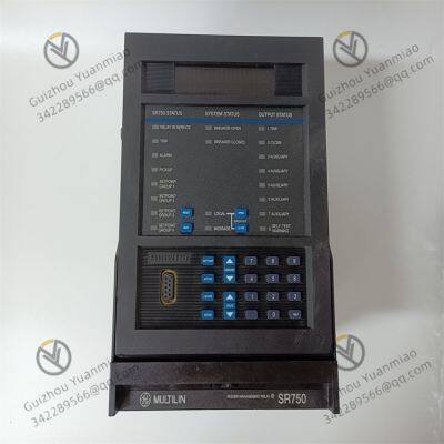
Iv. Human-computer Interaction and Parameter Configuration
Local Settings and display
The front panel keyboard is used to input protection parameters (such as rated current, trip threshold, delay time), and
the LCD display shows the motor operation status and parameters in real time.
Remote software configuration
By connecting the EnerVista 369 software through a computer, the parameters of multiple relays can be set in batches,
or the preset protection scheme templates can be imported to improve the debugging efficiency.
V. Typical Application Scenarios and Work Processes
Take the starting protection of three-phase motors as an example:
When the motor starts, the relay monitors the peak value and duration of the starting current to determine if it
exceeds the allowable starting time (to avoid locked rotor).
During normal operation, continuously monitor parameters such as the three-phase current balance degree and
winding temperature. If an overload occurs, trip with a delay according to the thermal accumulation model.
When an external shutdown signal is received or a fault is detected, the relay outputs a trip instruction and
simultaneously reports the fault code to the monitoring system through the communication port.
Summary
The GE 369-LO-0-M-F-E-0-0 digital relay realizes all-round protection and intelligent management of the motor
through the closed-loop logic of "real-time monitoring of electrical parameters + digital algorithm analysis +
automatic protection execution + two-way communication interaction". Its core advantages lie in high-precision
detection, flexible parameter configuration and industrial communication compatibility, and it is suitable for motor
system protection in scenarios such as chemical engineering, power, and manufacturing.

Send Inquiry to This Supplier


You May Also Like
-
GE VME-5565 Reflective Memory VME Node CardNegotiableMOQ: 1 Piece
-
GE VME-7807RC High-performance Single-board ComputerNegotiableMOQ: 1 Piece
-
GE VMIVME-2510B 64-bit TTL Digital Input/output BoardNegotiableMOQ: 1 Piece
-
GE VMIVME-2540-000 Intelligent ControllerNegotiableMOQ: 1 Piece
-
GE VMIVME-4116 Data Acquisition Control Board Card NegotiableMOQ: 1 Piece
-
GE VMIVME-4140 32-channel 12-bit Analog Output Circuit BoardNegotiableMOQ: 1 Piece
-
GE VMIVME-5565-110000 Reflective Memory Node CardNegotiableMOQ: 1 Piece
-
GE VMIVME-7459 Storage ModuleNegotiableMOQ: 1 Piece
-
GE VMIVME-7486 VMEbus CPU ModuleNegotiableMOQ: 1 Piece
-
GE VMIVME-7658 Single-board ComputerNegotiableMOQ: 1 Piece


