








 Contact Platform Support
 Help Center
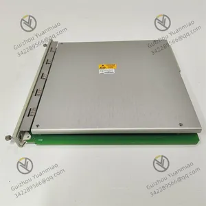
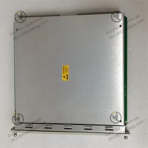
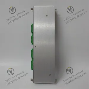
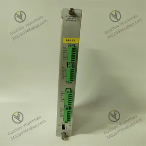
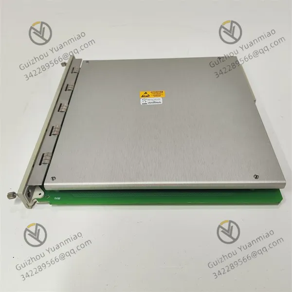
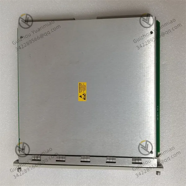
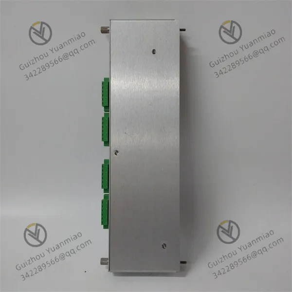
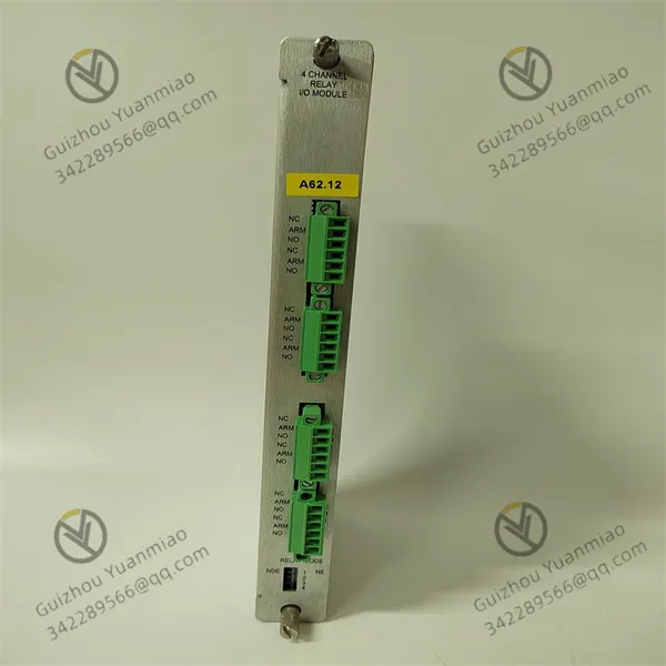
Bently Nevada 3500/32 4-channel Relay Module



Related Products
-
 Bently Nevada 3500 Monitoring System Series ModulesNegotiableMOQ: 1 Piece
 -
Bently Nevada 3500/33 Relay ModuleNegotiableMOQ: 1 Piece
-
Bently Nevada 3500/34 Triple Redundant Relay ModuleNegotiableMOQ: 1 Piece
-
Bently Nevada 3500/40 Monitor ModuleNegotiableMOQ: 1 Piece
-
Bently Nevada 3500/42 Monitor ModuleNegotiableMOQ: 1 Piece
Bently Nevada 3500/32 4-channel relay module
Detailed explanation of working principle
1. Core functional architecture
The 3500/32 relay module, as part of the Bently Nevada 3500 monitoring system, mainly functions to trigger alarm or
interlock actions based on mechanical condition monitoring data. Its core components include:
Microprocessor unit: It is responsible for receiving the monitor channel data (such as vibration, temperature and other
parameters) sent from the frame backplane and determining whether to trigger the relay action based on the preset
logic.
Relay drive circuit: When the microprocessor detects that the alarm condition is met, it sends a signal to the drive
circuit to control the relay coil to be powered on/off, achieving the switching of contact states.
Communication interface: Communicate with other modules (such as monitors, frame interface modules) through the
3500 system backplane to obtain real-time monitoring data and feedback the relay status.
2. Signal processing and logical judgment process
Data collection
The monitor module (such as the 3500/42 vibration monitor) converts the raw data collected by the sensor (such as
vibration amplitude and phase) into engineering units (such as μm, mm/s), and transmits it to the 3500/32 module
through the backplane bus.
Alarm threshold comparison
The 3500/32 module receives the current values of each monitoring channel and compares them with the
pre-configured Warning and Danger thresholds. For example:
When the vibration amplitude exceeds the warning threshold but does not reach the dangerous threshold, the
"warning" logic is triggered.
When the vibration amplitude exceeds the danger threshold, the "danger" logic is triggered.
Voting logic execution:
The module supports three alarm driver logic modes:
Bus relay mode: Alarm signals from multiple monitoring channels are summarized through "OR gate" logic. Once any
channel alarms, the relay is triggered to act.
Single relay mode: The relay only responds to the alarm signal of a specific monitoring channel (such as a channel that
only monitors the bearing temperature).
Independent relay mode: By combining alarm signals from multiple channels through "AND gates" or "OR gates",
complex logic is achieved (for example, the relay is triggered only when both vibration and temperature exceed the
limit).
3. Relay action mechanism
Coil control
When the microprocessor determines that the alarm condition is met, it outputs a high-level signal to the relay drive
circuit to energiize the coil (rated voltage 24Vdc).
The coil generates a magnetic field that attracts the armature, causing the normally open contact (NO) to close and
the normally closed contact (NC) to open.
Contact state maintenance:
The relay adopts a magnetic latch design. After the coil is energized, the contact state will be locked. Even if the coil is
de-energized, it will remain in the current state until a reset signal is received.
Contact capacity and lifespan:
The rated voltage of the contact is 250Vrms, and the maximum current is 5A (24Vdc/240Vdc). It can directly drive small
loads (such as indicator lights, solenoid valves) or control larger loads through an intermediate relay.
The mechanical life is ≥10⁷ operations, and the electrical life is ≥10⁵ full-load operations, ensuring long-term reliable
operation.
4. Status indication and Feedback
LED indicator light
OK LED: It flashes once per second during normal operation. If it goes off or remains on constantly, it indicates a
module failure (such as abnormal power supply or processor freeze).
TX/RX LED: It flashes when communication with other modules in the frame is normal and turns off when
communication is interrupted. It is used to diagnose backplane communication faults.
CH ALARM LED: It lights up when the corresponding channel relay triggers an alarm. It can be set to "locked" or
"non-locked" mode through software configuration (the locked mode requires manual reset, and the non-locked
mode automatically resets after the alarm condition disappears).
Status feedback signal:
The relay module can feed back the current contact status (such as normal, warning, dangerous) to the monitoring
system through the backplane, facilitating the recording and display by the upper computer software.
5. Collaborative work with the 3500 system
Power Supply and Communication
The module acquires a 24Vdc power supply through the 3500 frame backplane and communicates with other modules
using the RS-485 protocol, with a transmission rate as high as 115.2kbps.
Redundancy and Fault Tolerance
In the redundantly configured 3500 system, the primary and backup relay modules receive monitoring data
synchronously. When the primary module fails, the backup module automatically takes over the control to ensure the
continuous alarm function.
Software configuration
The relay module can be set as follows using the 3500/VM or DE software of Bently Nevada:
Define the alarm threshold and lag amount (for example, the danger threshold is 100μm and the lag amount is 10μm,
that is, it needs to be reduced to 90μm after the alarm to reset);
Configure the relay output mode (always on/always off);
Set the alarm delay (for example, the relay operates only after the alarm signal lasts for 2 seconds to avoid
misoperation caused by interference).

Send Inquiry to This Supplier


You May Also Like
-
Bently Nevada 3500/45 Displacement Monitoring ModuleNegotiableMOQ: 1 Piece
-
Bentley Nevada 3500/53 Overspeed Detection ModuleNegotiableMOQ: 1 Piece
-
Bently Nevada 3500/92 Communication Gateway ModuleNegotiableMOQ: 1 Piece
-
Bently Nevada 3500/93 Display Interface I/O ModuleNegotiableMOQ: 1 Piece
-
Bently Nevada 3500/94 Display Device MonitorNegotiableMOQ: 1 Piece
-
Bently Nevada 3500/95 Display Device MonitorNegotiableMOQ: 1 Piece
-
Bently Nevada 3500/50-01-00-01 Rotational Speed Measurement ModuleNegotiableMOQ: 1 Piece
-
BENTLY 3500/70 Expansion Monitoring ModuleNegotiableMOQ: 1 Piece
-
BENTLY 3500/72M Dual-channel Vibration Monitoring ModuleNegotiableMOQ: 1 Piece
-
Bently 3500/05-01-02-00-00-00 Framework ModuleNegotiableMOQ: 1 Piece


